Improved cutting unit and shaving head of a shaving device

Active Publication Date: 2018-05-31
KONINKLJIJKE PHILIPS NV
View PDF1 Cites 1 Cited by
  • Summary
  • Abstract
  • Description
  • Claims
  • Application Information

AI Technical Summary

Benefits of technology

The invention aims to meet three important requirements for a design, while also allowing for easy removal and insertion of internal cutting members. The design is simple and compact.

Problems solved by technology

Furthermore, it is clear that the cutting unit 6 does not allow the user to directly touch the internal cutting member at a moment when the internal cutting member is drivably connected to its rotative drive structure.
A general drawback of most of these known retainers is that the manual operations required for removing and inserting the internal cutting members relative to their cutting units are not easy for users to understand and / or perform and / or remember.
For example, the locking and unlocking of the retainers relative to their corresponding cutting units often is cumbersome, especially because most of these retainers are small parts which are difficult to operate accurately with the fingers, and which have very tiny locking parts which are difficult to discern with the naked eye.

Method used


Image

  • Improved cutting unit and shaving head of a shaving device
  • Improved cutting unit and shaving head of a shaving device
  • Improved cutting unit and shaving head of a shaving device

Examples


first embodiment

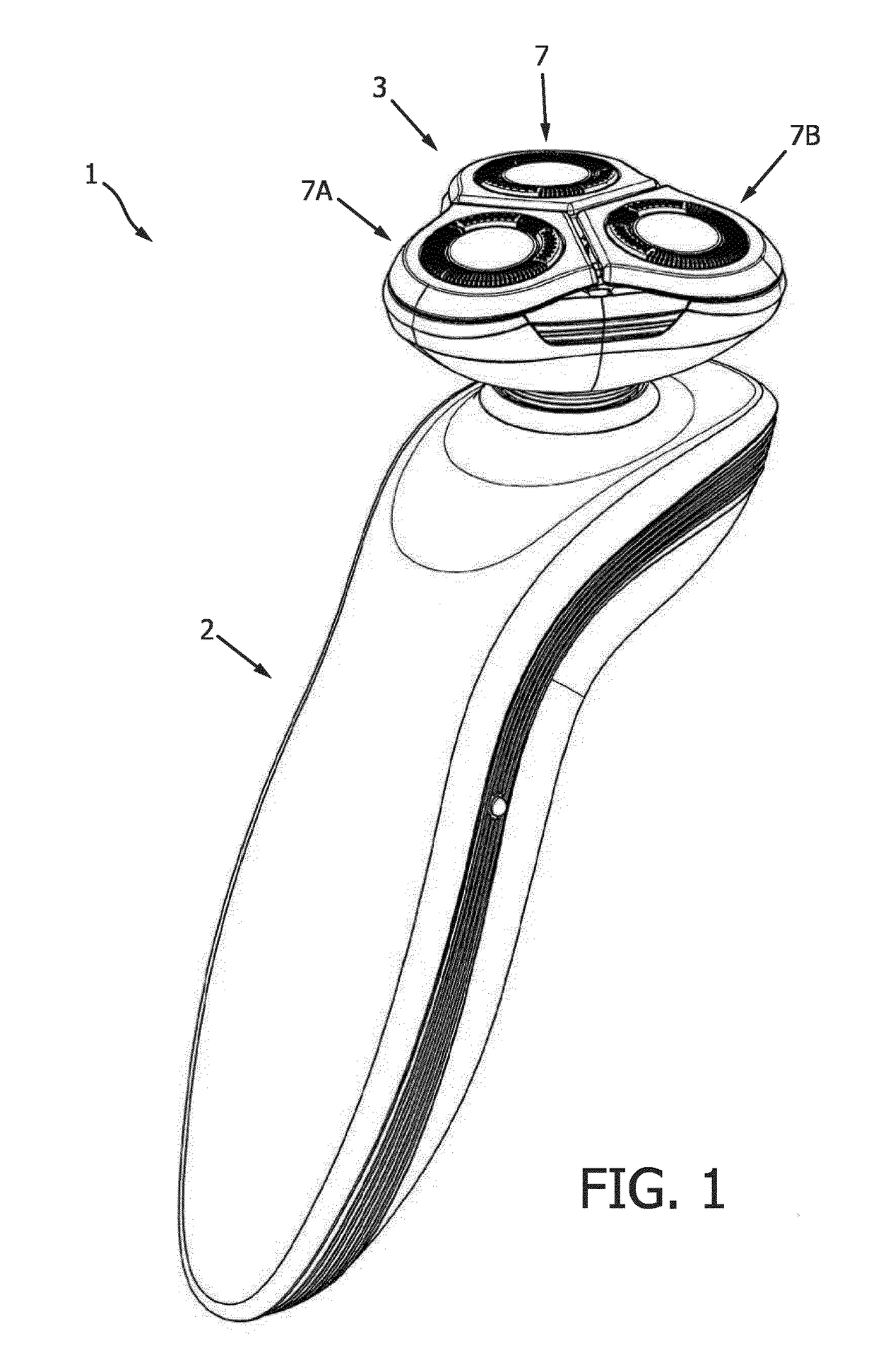
[0085]Reference is first made to FIGS. 1-4, which show the shaving device 1 based on the shaving head.

[0086]FIG. 1 shows that the shaving device 1 comprises the shaving device main body 2 and the shaving head 3 being connected thereto.

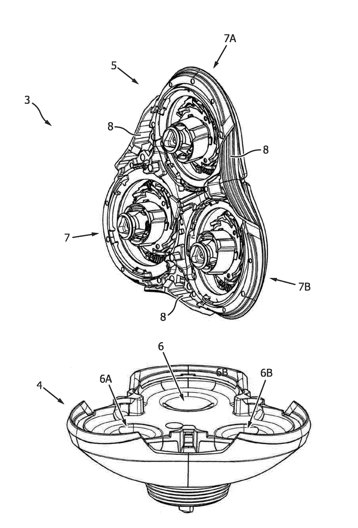
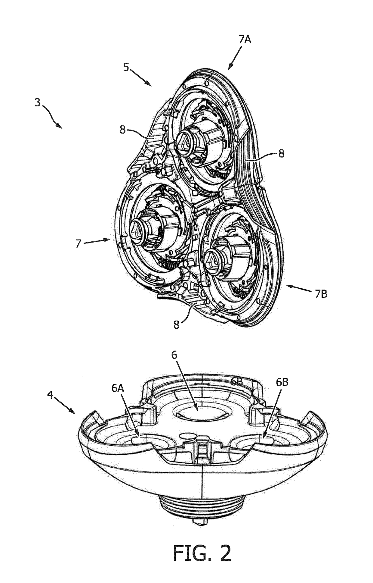
[0087]FIG. 2 shows that the shaving head 3 can be taken apart into the shaving head driving body 4 and the shaving head cutting body 5. The shaving head cutting body 5 has the frame 8, to which the three identical first cutting units 7, 7A, 7B of the shaving head 3 are connected. The shaving head driving body 4 has the three driving shafts 6, 6A, 6B for driving the three internal cutting members 22 of the three cutting units 7, 7A, 7B, respectively.

[0088]FIG. 3 shows that the first cutting unit 7 comprises the external cutting member 11 and the internal cutting member 12. In operation of the shaving head 3, the shown skin supporting member 14 of the shaving head cutting body 5 is suspended relative to the frame 8 of the shaving head cutting body 5, whi...

second embodiment

[0093]Reference is now made to FIG. 5, which shows the second cutting unit 207 for use in the abovementioned second embodiment of a shaving head according to the invention. The second cutting unit 207 comprises the external cutting member 211 and the internal cutting member 212. It is seen that the first central portion 221 and the second central portion 222 are mutually co-operating portions providing radial bearing support for the rotative movement about the rotation axis 210.

[0094]Furthermore it is seen that, in the shown example, the magnet 230 is associated with, and arranged in, the second central portion 222 for providing the abovementioned magnetic attraction between the first central portion 221 and the second central portion 222. In the shown example, the first central portion 221 comprises magnetizable material.

[0095]In FIG. 5, the magnetic axis of the magnet 230 has been indicated by means of the depicted two-way arrow, while the corresponding magnetic field of the magne...

third embodiment

[0097]Reference is now made to FIG. 6, which shows a cutting body 305 of the abovementioned third embodiment of a shaving head according to the invention. This shaving head cutting body 305 comprises the two third cutting units 307 and 307A, which are connected to the frame 308 of the shaving head cutting body 305. The third cutting unit 307 comprises the external cutting member 311 and the internal cutting member 312. It is seen that the first central portion 321 and the second central portion 322 are mutually co-operating portions providing radial bearing support for the rotative movement about the rotation axis 310. Similarly, the third cutting unit 307A comprises the external cutting member 311A and the internal cutting member 312A, while the first central portion 321A and the second central portion 322A are mutually co-operating portions providing radial bearing support for the rotative movement about the rotation axis 310A.

[0098]Furthermore, it is seen that, in the shown examp...


PUM


Abstract

The invention relates to a rotary cutting unit (207) of a shaving head of a shaving device, which cutting unit comprises an external cutting member (211) and an internal cutting member (212). In interconnected condition, a holding force prevents the external and internal cutting members from moving apart. Said holding force is at least exerted by a first central portion (221) of the external cutting member upon a second central portion (222) of the internal cutting member, and / or vice versa. Said holding force may for example be provided by means of a snap connection or magnetic attraction between said first and second central portions. As compared to rotary cutting units of existing shaving heads, the invention meets various known desirable design requirements, while at the same time providing for manual removal and insertion of the internal cutting members in a very easy, comfortable and intuitive manner, and the structure to achieve all this being non-complex and compact.

Description

FIELD OF THE INVENTION[0001]The invention relates to a shaving device for shaving hairs. More specifically, the invention relates to a cutting unit for use in a shaving device for shaving hairs, said cutting unit comprising:[0002]an external cutting member comprising a shaving surface, which is interrupted by an apertured structure for allowing hairs to pass; and[0003]an internal cutting member, which is drivable for rotative movement relative to the external cutting member about a rotation axis and along said apertured structure in the shaving surface of the external cutting member for cutting through hairs passing said apertured structure;[0004]and wherein:[0005]the external cutting member and the internal cutting member have:[0006]an interconnected condition, in which the external cutting member and the internal cutting member are mutually interconnected for operation of the cutting unit, and[0007]a disconnected condition, in which the external cutting member and the internal cut...

Claims


Application Information

Patent Timeline
IPC IPC(8): B26B19/14
CPCB26B19/141B26B19/14
Inventor GODLIEB, ROBERT
Owner KONINKLJIJKE PHILIPS NV
Why Eureka
Try Eureka