Teatcup liner and a teatcup

Active Publication Date: 2013-09-19
DELAVAL HLDG AB
View PDF8 Cites 3 Cited by
  • Summary
  • Abstract
  • Description
  • Claims
  • Application Information

AI Technical Summary

Benefits of technology

The present invention is a teatcup liner that can be easily manufactured and adapted to different uses. It is designed in a modular way, allowing for the addition of further functions. The liner includes a ring module that can be easily added to the liner, providing a flexible way to add new functions. The liner also includes a first section that remains unchanged regardless of the position or function of the other sections, and a second section that maintains its function of exerting pressure on the teat. The invention also includes a functional member that emits light, particularly UV-light, to help prevent bacterial growth and other microorganism growth in the liner, thereby maintaining a safe level of bacteria in the milk. Overall, this invention provides a flexible and efficient way to meet different needs while ensuring a safe and high-quality product.

Problems solved by technology

However, such additional functions tend to make the manufacture of the teatcup more complicated and hence more expensive.

Method used


Image

  • Teatcup liner and a teatcup
  • Teatcup liner and a teatcup
  • Teatcup liner and a teatcup

Examples


first embodiment

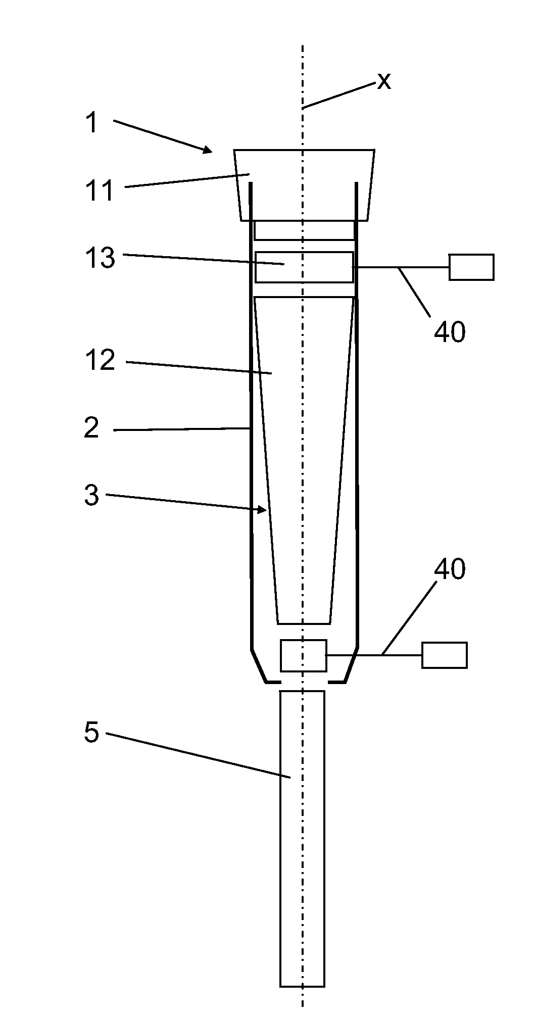
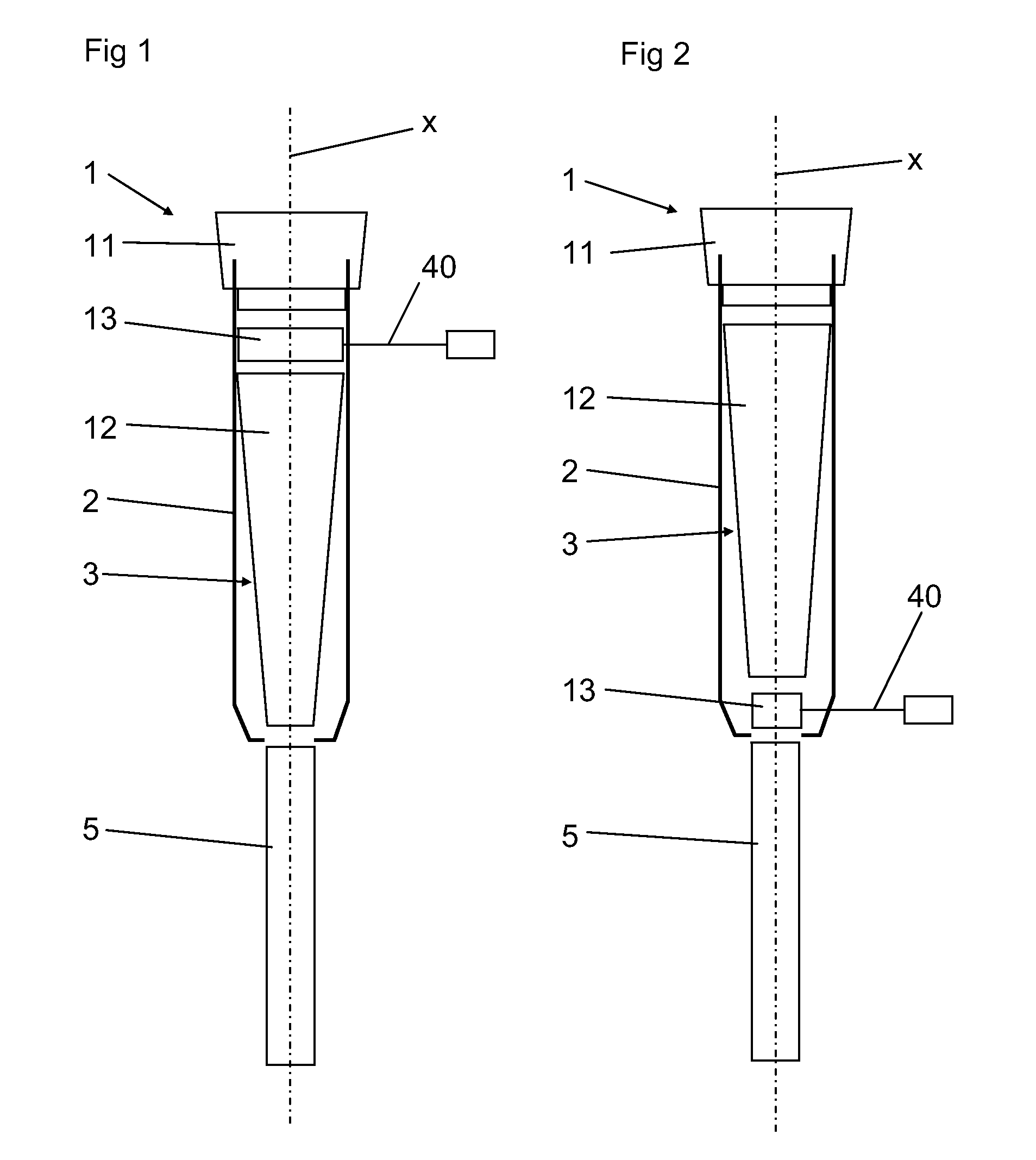
[0034]FIG. 1 refers to a first embodiment and discloses a teatcup 1 to be attached to a teat of an animal for the performance of a milking operation. The teatcup 1 comprises a teatcup shell 2 and a teatcup liner 3 mounted in the teatcup shell 2. The teatcup liner 3 defines an inner space 4, see FIGS. 3, 4, 6 and 7, for receiving the teat. A longitudinal centre axis x extends through the inner space 4. The teatcup liner is connected or connectable to a milk-conveying member 5.

[0035]The teatcup liner 3 of the first embodiment (disclosed in an exploded side view) comprises or is composed of three separate annular sections 11-13. The annular sections 11-13 are shown separated in FIG. 1, but are attached to each other when the teatcup liner 3 is used. The annular sections 11-13 are arranged successively after each other along the longitudinal centre axis x.

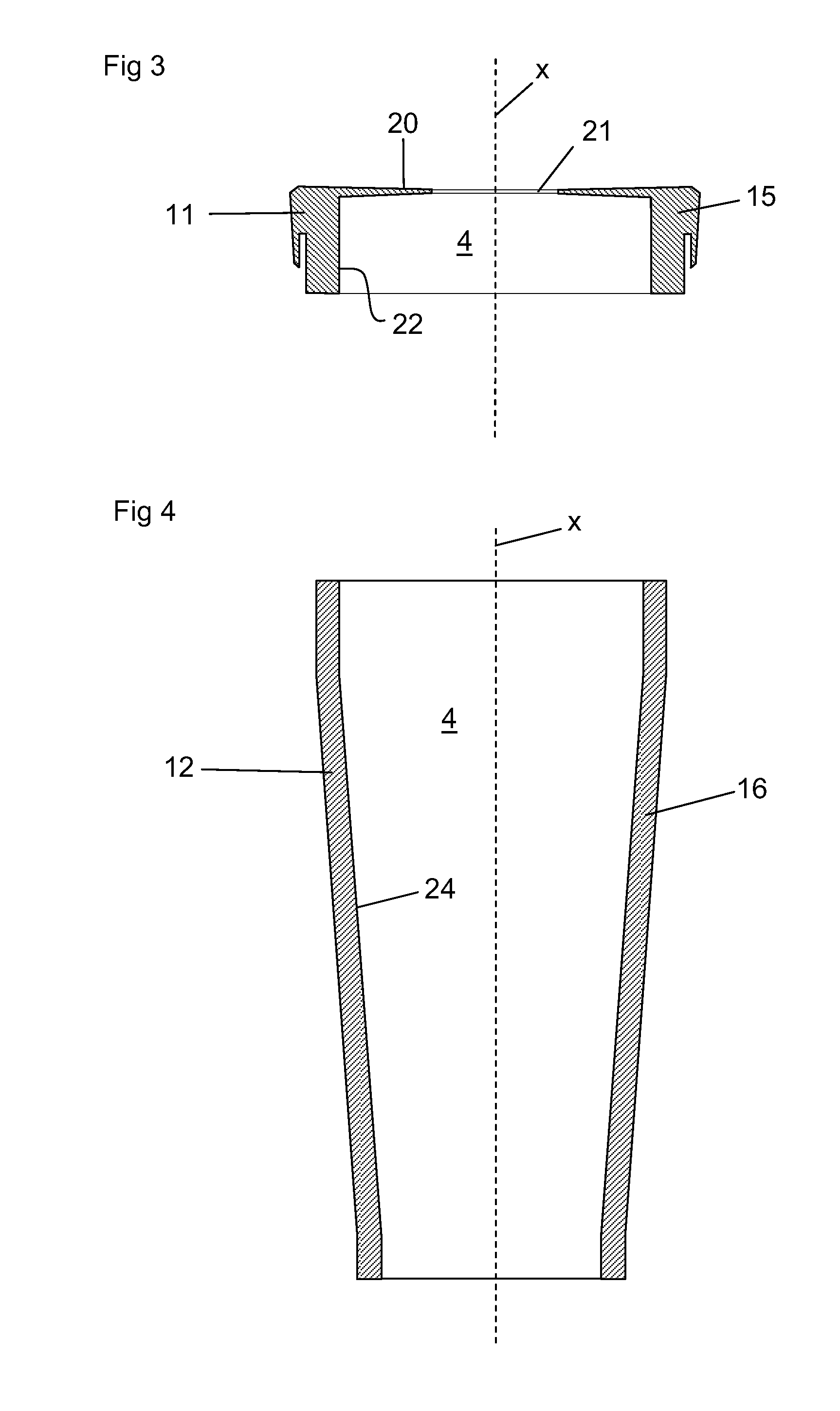
[0036]A first section 11 of the sections 11-13 forms an upper part 15 of the teatcup liner 3, see FIG. 3. The upper part 15 comprises...

third embodiment

[0061]In FIGS. 1, 2, 4 and 10, the second section 12 forming the tube part 16 is shown with a conical or tapering shape, i.e. the diameter at the upper end is longer than the diameter at the lower end of the tube part 16. It is to be noted that the tube part 16 of the teatcup liner 3 according to an alternative embodiment may have a cylindrical shape with a constant, or substantially constant, diameter along the length of the tube part 16. In this embodiment, one and the same third section 13, forming the ring module 17 with the functional member, may then be provided between the first section 11 and the second section 12, below the second section 12 or between the second section 12 and the milk-conveying member 5. This cylindrical configuration of the tube part 16 also permits the third section 13 and the fourth section 14 of the third embodiment to be identical at least with respect to the dimensions.


PUM


Abstract

A teatcup (1) and a teatcup liner (3) for a teatcup to be attached to a teat of an animal for the performance of a milking operation. The teatcup liner defines an inner space for receiving the teat and a longitudinal center axis (x) extending through the inner space. The teatcup liner is composed of at least three separate annular sections, which are attached to each other and arranged successively after each along the longitudinal center axis. A first section (11) forms an upper part having an opening for allowing the teat to be introduced into the inner space. A second section (12) forms a tube part engaging the teat during the milking operation. A third section (13) forms a ring module having an inner surface facing the inner space. The ring module includes a functional member providing an additional function to the milking operation.

Description

THE FIELD OF THE INVENTION AND PRIOR ART[0001]The present invention refers to a teatcup liner according to the preamble of claim 1. The invention also refers to a teatcup comprising such a teatcup liner. It is known to provide a teatcup or a teatcup liner with various additional functions as can be seen in the prior art documents discussed below. However, such additional functions tend to make the manufacture of the teatcup more complicated and hence more expensive.[0002]US 2009 / 0126637 discloses a teatcup liner for a teatcup to be attached to a teat of an animal for the performance of a milking operation, the teatcup liner defining an inner space for receiving a teat. The teatcup liner may be composed of two separate sections which are attached to each other and arranged successively after each along a longitudinal centre axis of the teatcup liner. A first of the sections forms an upper part having an opening for allowing the teat to be introduced into the inner space, and a tube p...

Claims


Application Information

Patent Timeline
IPC IPC(8): A01J5/06
CPCA01J5/06A01J5/08A01J5/007A01J5/16
Inventor ALVEBY, NILSLIDMAR, ANNELI
Owner DELAVAL HLDG AB
Why Eureka
Try Eureka