Tool-holding device, work machine with the tool-holding device, as well as a method for positioning a tool on a tool-holding device

Active Publication Date: 2021-02-18
SCHLEUNIGER
View PDF2 Cites 0 Cited by
  • Summary
  • Abstract
  • Description
  • Claims
  • Application Information

AI Technical Summary

Benefits of technology

The invention aims to improve the handling of tools on a tool-holding device by creating a tool-holding device that reduces the risk of injury and enables easy and quick replacement of tools. Additionally, a work machine with the tool-holding device and a method for positioning tools on the device should be created to help save time and facilitate the use of the tool-holding device in workplaces.

Problems solved by technology

The disadvantage of this well-known solution is that, the user of the machine tool requires a plurality of handles for arranging and attaching the tool in order to engage the two locking parts with one another when assembling the tool, as well as requiring a plurality of handles for detaching and removing the tool in order to disengage the two locking parts during disassembly.

Method used


Image

  • Tool-holding device, work machine with the tool-holding device, as well as a method for positioning a tool on a tool-holding device
  • Tool-holding device, work machine with the tool-holding device, as well as a method for positioning a tool on a tool-holding device
  • Tool-holding device, work machine with the tool-holding device, as well as a method for positioning a tool on a tool-holding device

Examples


Embodiment Construction

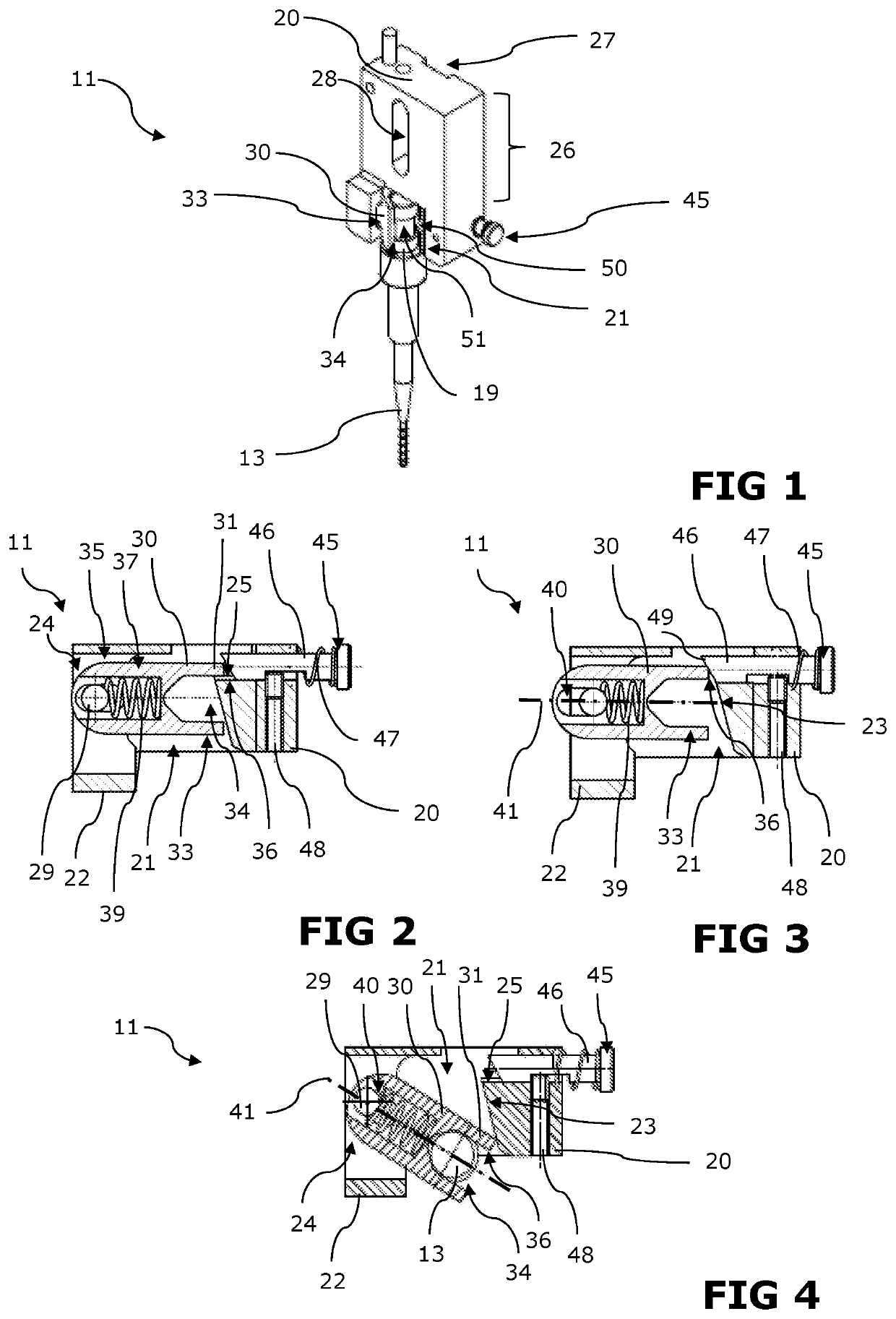
[0086]FIG. 1 to FIG. 4 show a tool-holding device 11 for holding a tool 13. The tool-holding device 11 comprises a retaining unit 20 and a lock unit 30. A receiving section 21 for holding the lock unit 30 is arranged on the retaining unit 20, wherein the receiving section 21 comprises a holding section 23 and a fixing stop 25 for temporarily fixing the lock unit 30 in a fixing position. In the fixing position, the lock unit 30 is completely arranged in the receiving section 21. The fixing stop 25 prevents an independent or undesirable opening of the lock unit 30 at a work machine during operation. The holding section 23 is wedge-shaped so that the lock unit 30 can slide along the wedge-shaped holding section 23 at least in sections when closing.

[0087]Furthermore, a receiving stop 22 is provided on the retaining unit 20 for positioning the lock unit 30 in the receiving position. Thereby, the lock unit 30 is stopped when transferred to the receiving position, wherein the lock unit 30 ...


PUM


Abstract

A tool-holding device (11) for holding a tool (13) on a work machine with a retaining unit (20) and with a lock unit (30). The lock unit (30) can be transferred from a receiving position into a fixing position, and the retaining unit (20) comprises a receiving section (21) for holding the lock unit (30) at least in sections. The lock unit (30) comprises a tool-holding section (33) for holding a tool (13) in a pre-positioned manner. A work machine with this tool-holding device and a method for positioning a tool (13) on a work machine are also disclosed.

Description

[0001]This application claims priority from European patent application serial no. 19191585.9 filed Aug. 13, 2019.FIELD OF THE INVENTION[0002]The invention relates to a tool-holding device, a work machine with the tool-holding device and a method for positioning a tool on a tool-holding device.BACKGROUND OF THE INVENTION[0003]The conversion from a first tool to another tool in a work machine, using which different workpieces are machined, usually requires a stopping of the work machine. In order to ensure that a standstill of the work machine scarcely plays an overall role in the industrial production of workpieces, the user of the machine must be able to carry out the conversion of the machine from a first tool to another tool with a minimal expenditure of time.[0004]In the case of cable processing machines, the manufacturing processes are carried out semi-automatically so that the user of a cable processing machine must be able to arrange a tool at the appropriate location on the ...

Claims


Application Information

Patent Timeline
IPC IPC(8): B23Q3/12B23B31/103
CPCB23Q3/12B23Q2220/002B23B31/103B23Q13/00B23Q1/72B21D28/34B21D37/04B26D7/2614B25D17/08Y10T279/17761B25D2217/0038
Inventor IMFELD, RUEDIIMHOLZ, KLEMENSBÜRGISSER, MARCO
Owner SCHLEUNIGER
Why Eureka
Try Eureka