Optical viewfinder and optical apparatus using same

Active Publication Date: 2013-08-29
CANON KK
View PDF23 Cites 6 Cited by
  • Summary
  • Abstract
  • Description
  • Claims
  • Application Information

AI Technical Summary

Benefits of technology

The patent describes an optical viewfinder that can show both an image of an optical object and information about the status of the optical apparatus in a clear and easily readable way. This is made possible because the viewfinder has a self-luminous display element and a non-self-luminous display element that can block off the finder light. This allows the photographer to see both the optical image and the status information simultaneously.

Problems solved by technology

However, the luminance of the display portion is low because of utilizing reflected diffusion light through a liquid crystal polymer.
Thus, the liquid crystal display method has the drawback that luminescence from the liquid crystal display portion cannot visually be confirmed in a relatively bright place.
For example, when an object (person) wearing a black costume overlaps with the liquid crystal display portion appearing black, the information given by the liquid crystal display is very hard to visually recognize.
However, such a method cannot be said as being superior in terms of a function of displaying the image-taking enable region because an object image appears similarly in both the image-taking unable region and the image-taking enable region.

Method used


Image

  • Optical viewfinder and optical apparatus using same
  • Optical viewfinder and optical apparatus using same
  • Optical viewfinder and optical apparatus using same

Examples


embodiment

[0031]The embodiment of the present invention will be described in detail below with reference to FIGS. 1A to 6.

[0032]It is to be noted that the same component is denoted by the same reference symbol in FIGS. 1A to 6.

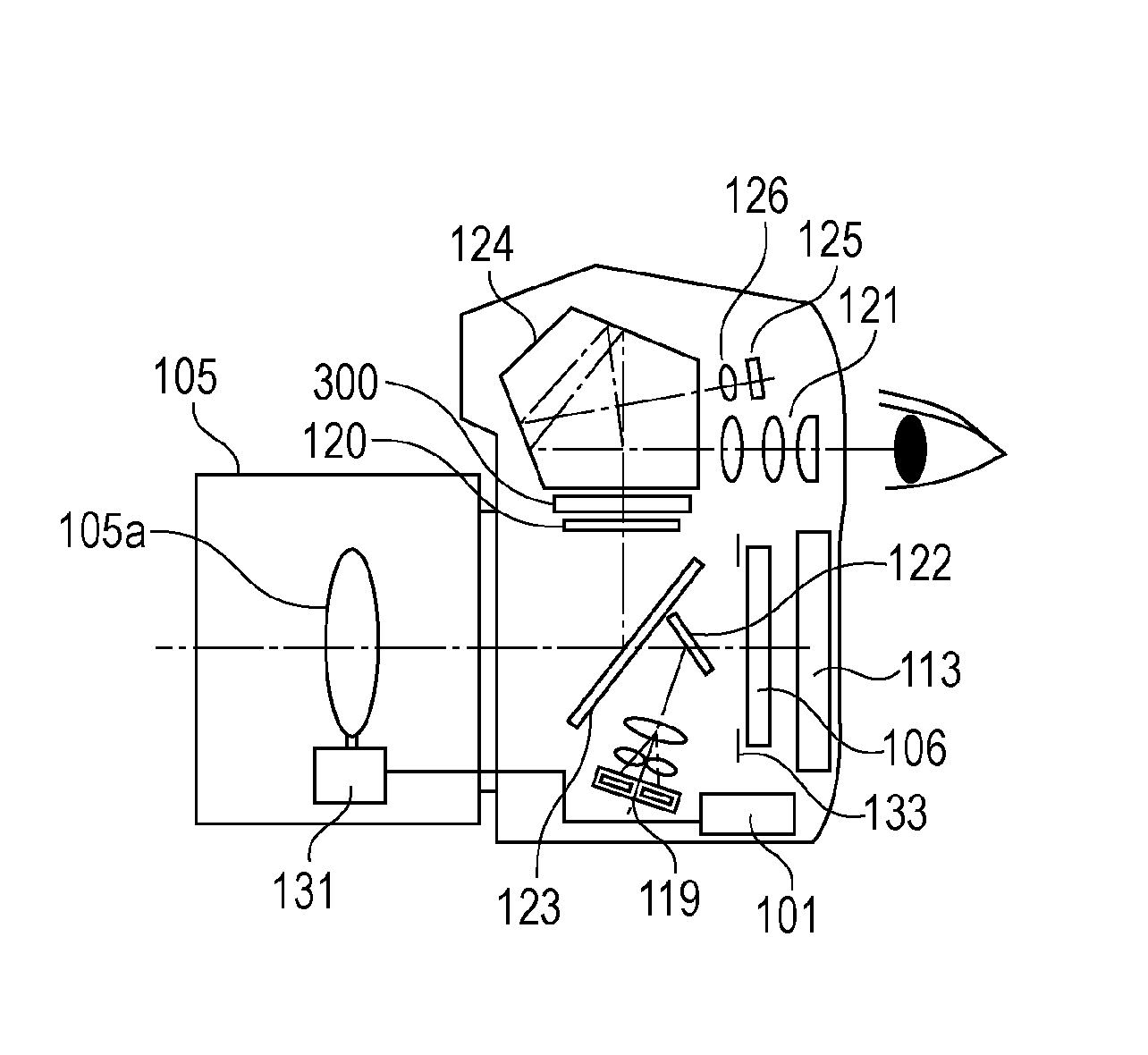
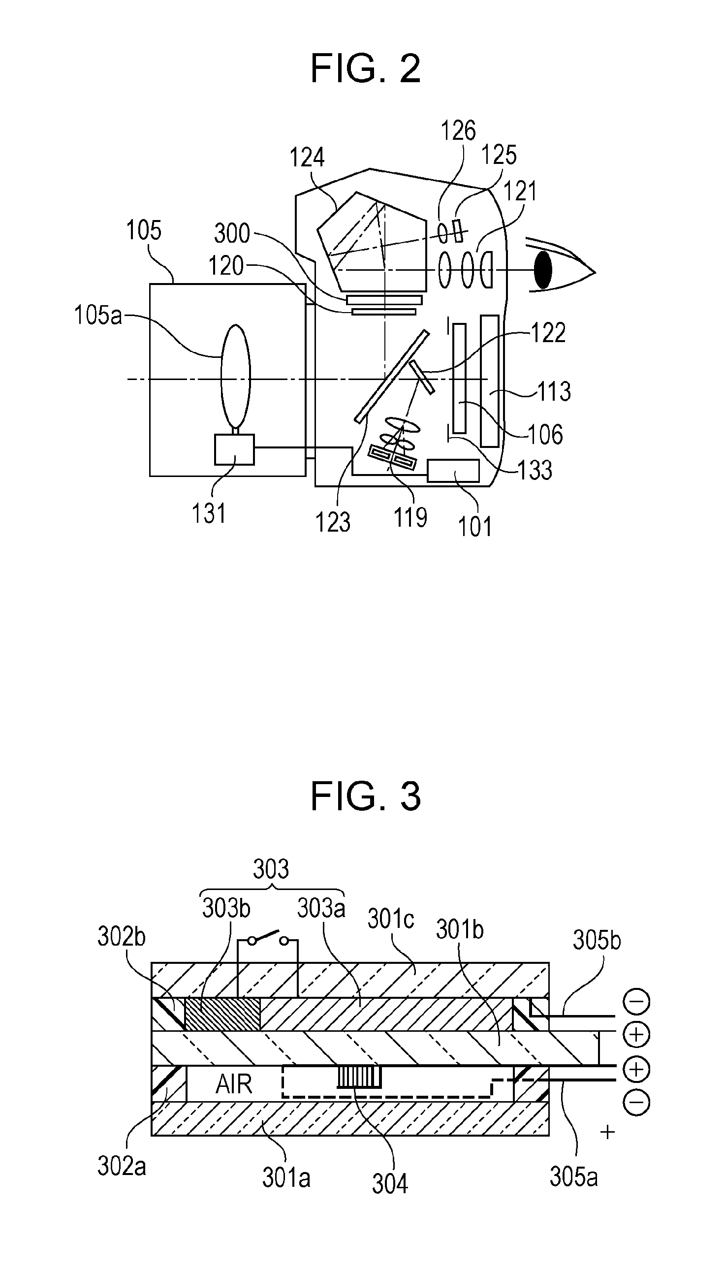
[0033]FIG. 2 is a schematic view illustrating a structure of a digital single-lens reflex camera, i.e., an example of an image pickup apparatus, to which the present invention is applied.

[0034]In FIG. 2, reference symbol 101 denotes a CPU (Central Processing Unit). Operation of the camera is controlled by the CPU 101. An imaging lens 105 serves as an objective lens and focuses light from an object scene on a CCD or CMOS sensor 106 which is an example of an image pickup element (image pickup unit). The imaging lens 105 includes a lens unit 105a and a lens driving unit 131 (e.g., ultrasonic motor USM). While the imaging lens 105 in FIG. 2 is illustrated as including a single piece lens in the lens unit 105a for the sake of simplicity, the lens unit 105a may actually inclu...


PUM


Abstract

An optical viewfinder to observe an object image focused as a primary image by an objective lens includes a first display unit of self-luminous type and a second display unit of non-self-luminous type. The first display unit is arranged at a position closer to a primary image plane of the objective lens than the second display unit in a direction of an optical axis.

Description

BACKGROUND OF THE INVENTION[0001]1. Field of the Invention[0002]The present application is related to an optical viewfinder, and more particularly to an optical viewfinder including a display element disposed in a viewing optical path of the optical viewfinder and to an optical apparatus, e.g., an image pickup apparatus or an observation apparatus, using the optical viewfinder.[0003]2. Description of the Related Art[0004]In order to increase an amount of information to be displayed on an optical viewfinder of a camera, it has recently been generalized to arrange, near a focusing plate positioned in a primary image plane of an imaging lens, a display panel made of a polymer network liquid crystal display (PNLCD) that has a high transparency and that does not darken a field image in the optical viewfinder.[0005]On that occasion, an information display portion using a liquid crystal is basically set to block off field light and to appear black.[0006]Such a non-self-luminous display por...

Claims


Application Information

Patent Timeline
IPC IPC(8): H04N5/232
CPCH04N5/23293G03B17/20
Inventor IRIE, YOSHIAKI
Owner CANON KK
Why Eureka
Try Eureka