Eureka AIR delivers breakthrough ideas for toughest innovation challenges, trusted by R&D personnel around the world.

Engineered stress state with multi-well completions

a stress state and multi-well technology, applied in the direction of earthwork drilling, fluid removal, borehole/well accessories, etc., can solve the problems of inordinate time needed to drain a field, uneconomic development, and high cost, so as to and reduce the cost of development.

Active Publication Date: 2018-05-31
CONOCOPHILLIPS CO
View PDF1 Cites 26 Cited by
  • Summary
  • Abstract
  • Description
  • Claims
  • Application Information

AI Technical Summary

Benefits of technology

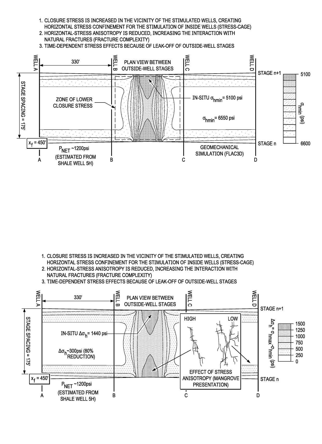
The patent text discusses a method called "hydraulic fracturing" which involves using high pressure to create fractures in underground formations. The text explains that when there is a high value of horizontal stress anisotropy (a measure of how strong the stress is) in a formation, it can prevent fractures from spreading and growing more complex. The text describes a method called a "stress cage" which helps to focus the energy of the hydraulic fractures closer to the wells, making the process more effective. The stress cage does not refer to the pressure in the wellbore region which can affect fracture initiation. Overall, the patent text explains how hydraulic fracturing can be improved by using a stress cage to increase the efficiency of the process.

Problems solved by technology

Without hydraulic fracturing, the time needed to drain a field would be inordinately long—in a tight field it could be in the order of hundreds of years.
The only way to drain the oil in a reasonable time is to drill more wells—e.g., up to 40 wells per square mile in a tight field—a very expensive undertaking, or to fracture the field.
Fracture stimulation not only increases the production rate, but it is credited with adding to reserves—9 billion bbl of oil and more than 700 Tscf of gas added since 1949 to US reserves alone—which otherwise would have been uneconomical to develop.
When the well is shut in and then reinjected, the fluid movement moves the debris to the ends of the fractures, causing increased pressures at the end, and thus further propagating the fracture in a direction perpendicular to the initial fracture.
Although hydraulic fracturing is quite successful, even incremental improvements in technology can mean the difference between cost effective production and reserves that are uneconomical to produce.

Method used


Image

  • Engineered stress state with multi-well completions
  • Engineered stress state with multi-well completions
  • Engineered stress state with multi-well completions

Examples


Embodiment Construction

[0105]During hydraulic fracture propagation, three regions may be identified from the pressure response and are referred to as: 1) near-well, that extends tens of inches; 2) mid-field, that extends tens of feet; and 3) far-field, that extends hundreds of feet from the wellbore. Each region can experience simple, tortuous, and complex fracture behavior creating unique pressure signatures.

[0106]For decades the oil industry has struggled to overcome near-wellbore fracture complexity during fracturing treatments, particularly in low-permeability, naturally fractured hard-rock reservoirs, because complexity near the wellbore reduces penetration of the fracture deeper into the reservoir. Yet at the same time, complexity is desired further away from the wellbore in order to sufficiently increase contact and drainage. A number of techniques have been created to diagnose and remediate these conditions to enable extension of created fractures and successful placement of proppant deep in the r...


PUM


Abstract

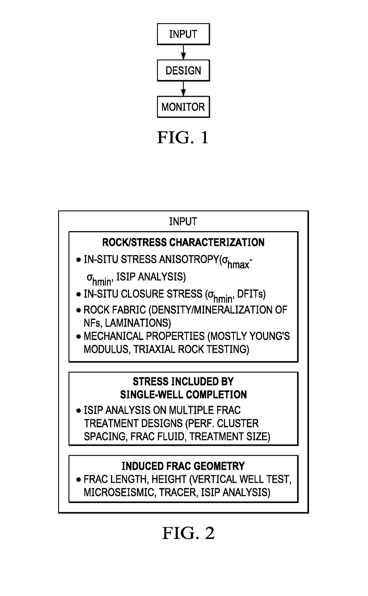
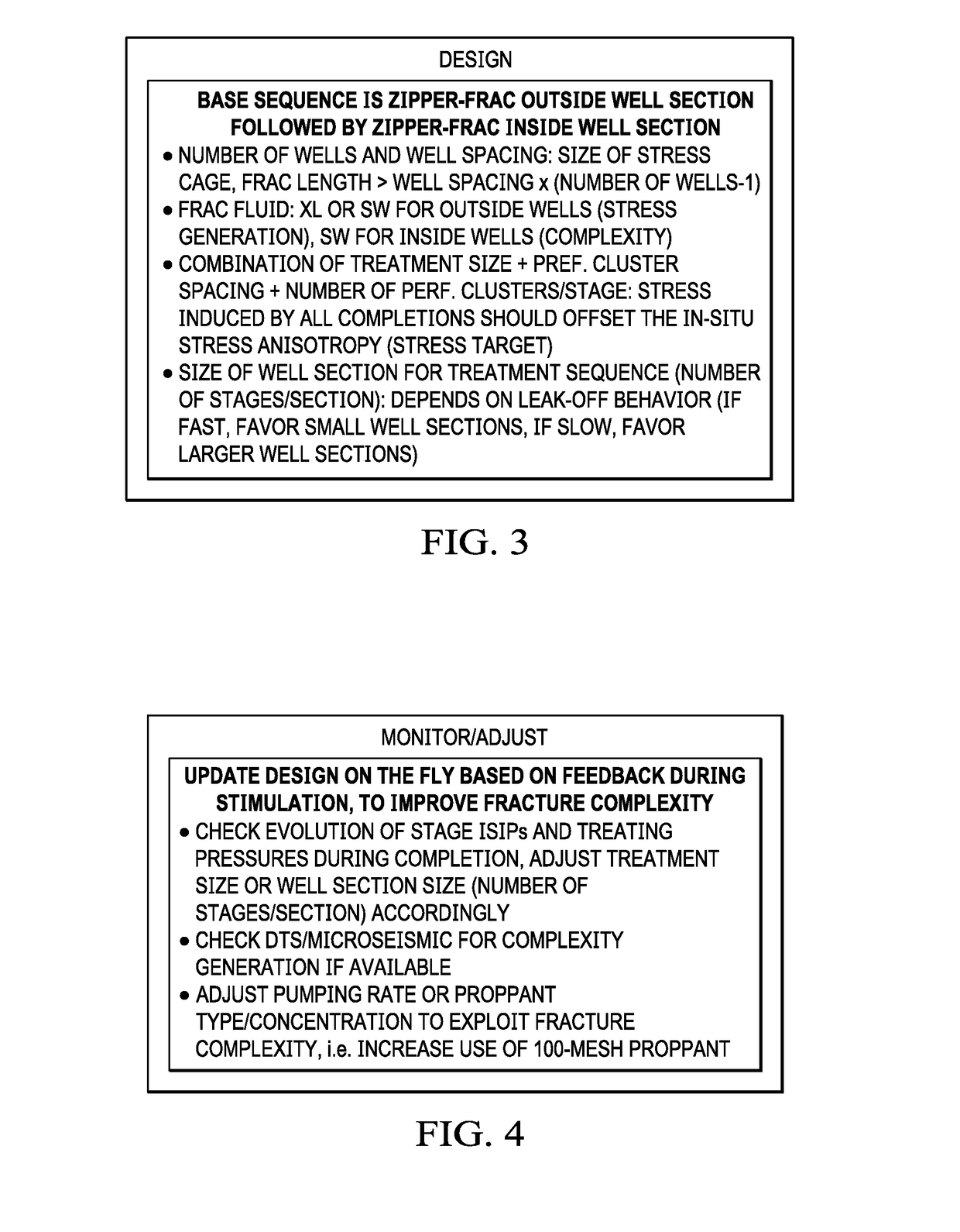
This disclosure describes a method for fracturing a well to improve productivity, by simulating zipper fracturing in such a way as to generate stress cages, thus minimizing anisotropy in a zone where fracture complexity is desired.

Description

PRIOR RELATED APPLICATIONS[0001]This application claims priority to U.S. provisional application Ser. Nos. 62 / 427,262 and 62 / 427,280, both filed on Nov. 29, 2016. Each of these applications is incorporated herein in their entirety for all purposes.FIELD OF THE DISCLOSURE[0002]The disclosure generally relates to a method of improved hydraulic fracturing by engineering a favorable state of stress in a multiwell reservoir completion. Specifically, stress cages are used to control the stresses. By designing the timing, sequence and spacing of hydraulic fracturing operations across multiple wells to create a near-isotropic stress state, the degree of fracture complexity and the amount of surface area induced during fracturing operations will be greatly enhanced.BACKGROUND OF THE DISCLOSURE[0003]Hydraulic fracturing or “fracking” is the propagation of fractures in a rock layer by a pressurized fluid. The oil and gas industry uses hydraulic fracturing to enhance subsurface fracture systems...

Claims


Application Information

Patent Timeline
Patent Type & Authority Applications(United States)
IPC IPC(8): E21B41/00E21B43/26E21B49/00
CPCE21B41/0092E21B43/26E21B49/00E21B41/00
Inventor ROUSSEL, NICOLAS P.LESSARD, MIKE D.
Owner CONOCOPHILLIPS CO
Why Eureka
Eureka Blog
Learn More