Method and device for determining the position of a vehicle

a technology for determining the position of a vehicle and a vehicle body, which is applied in the direction of measuring devices, using reradiation, instruments, etc., can solve the problem that the position of the vehicle in this way is unnecessarily complicated

Active Publication Date: 2018-05-31
ROBERT BOSCH GMBH
View PDF20 Cites 18 Cited by
  • Summary
  • Abstract
  • Description
  • Claims
  • Application Information

AI Technical Summary

Benefits of technology

[0036]In accordance with the present invention, this angular information is additionally incorporated into the digital map during the creation of the digital map. That is, for the detected objects the direction is also indicated from the position or location at which the detected objects were detected by the radar sensor unit. This is because the GNS vehicle position corresponds to the location of the radar measurement using the radar sensor unit, at least within the limit of measurement precision. When there is a determination of position based on such a digital map, such a direction vector, or a plurality of such direction vectors, is then likewise determined for the detected objects. The more the ascertained direction vectors agree with the direction vectors of the digital map, the higher the probability is that the objects detected during the determination of the position of the vehicle are the objects in the digital map. A matching between the radar image, which is based on the radar data and was ascertained during the determination of the position of the vehicle, and the digital map, which is also based on radar data, is thus simplified.
[0041]In order to distinguish whether the detected objects are stationary or mobile objects, according to a specific embodiment it is provided that the detected objects are assigned a speed by a radar measurement. Thus, preferably a respective speed of the detected objects is determined or measured. In this way, a distinction between mobile and stationary objects can advantageously be made.
[0042]According to a specific embodiment, a speed threshold value is provided above which a detected object is classified as a mobile object and below which a detected object is classified as a stationary object. The provision of such a threshold value can advantageously compensate or take into account possible measurement imprecision in the radar measurement.
[0045]According to a specific embodiment, it is provided that the fitting is carried out using an iterative closest point algorithm and / or a particle-based algorithm. Through the provision of these algorithms, an efficient compensation calculation or an efficient fitting can advantageously be brought about.

Problems solved by technology

A matching between the digital map and the radar image ascertained during the determination of position of the vehicle would in this way unnecessarily be made more difficult.

Method used


Image

  • Method and device for determining the position of a vehicle
  • Method and device for determining the position of a vehicle
  • Method and device for determining the position of a vehicle

Examples


Embodiment Construction

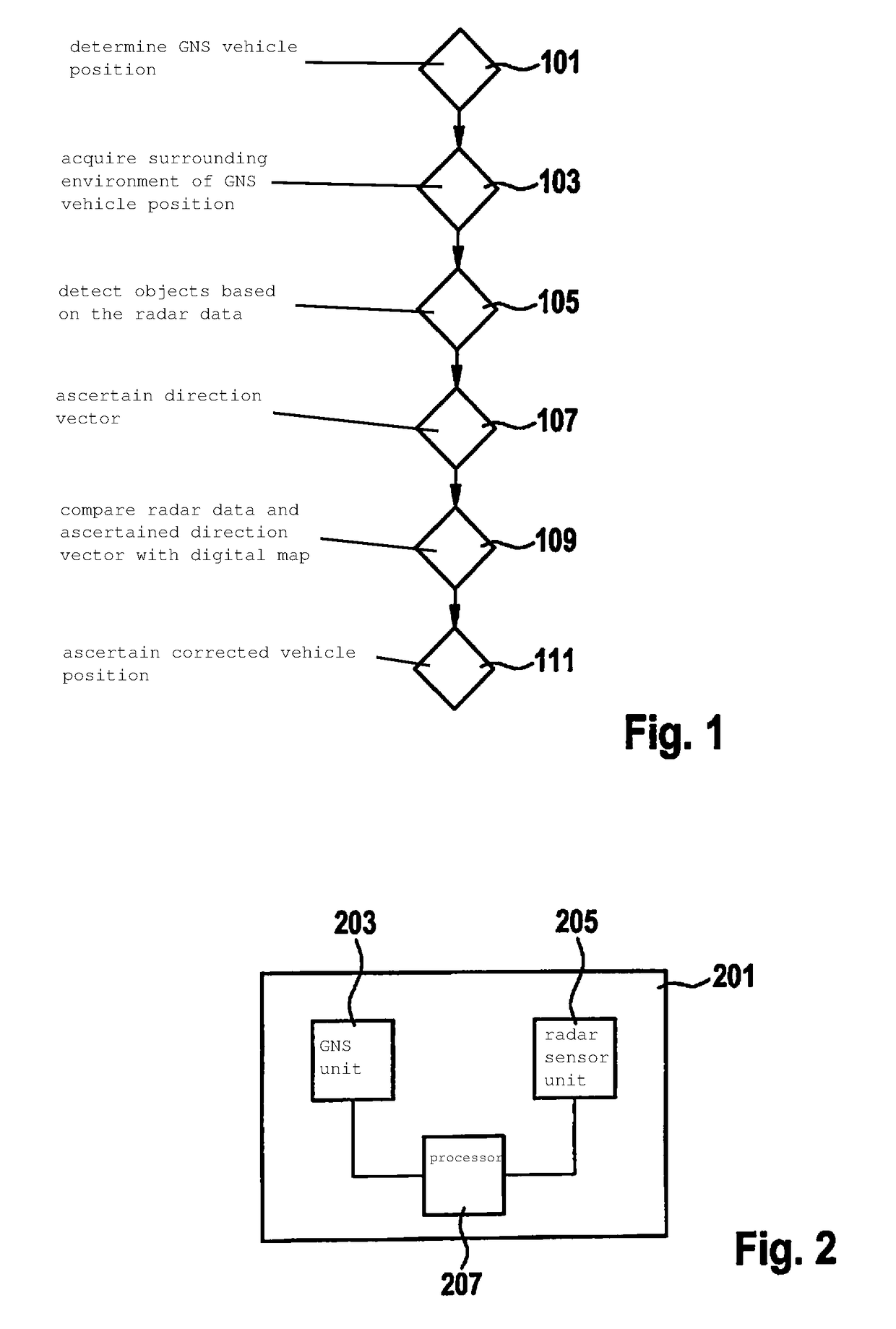
[0054]FIG. 1 shows a flow diagram of a method for determining the position of a vehicle.

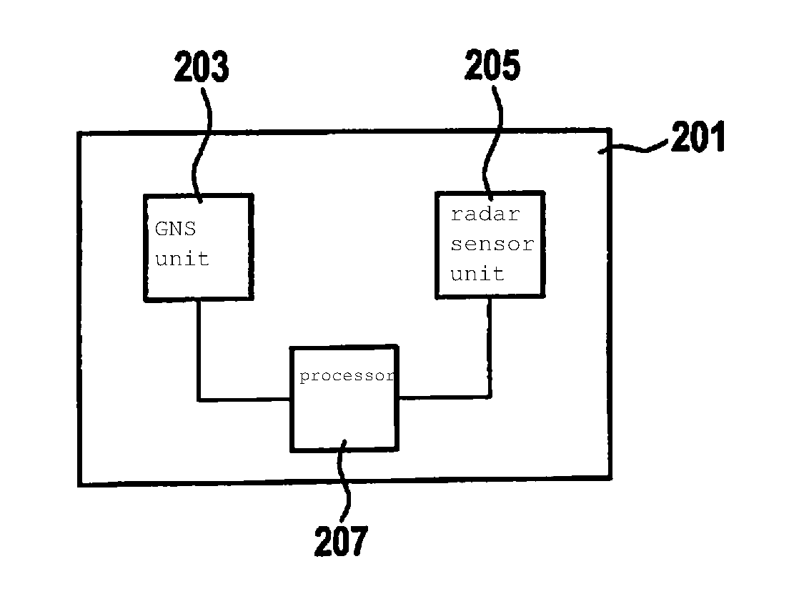
[0055]In a step 101, a GNS vehicle position is determined using a GNS unit. In a step 103, a surrounding environment of the GNS vehicle position is acquired by sensors, using a radar sensor unit of the vehicle, in order to ascertain radar data corresponding to the acquired environment. That is, in particular a radar image of the surrounding environment of the GNS vehicle position is ascertained. In the sense of the present invention, a radar sensor unit includes in particular one or more radar sensors.

[0056]In the sense of the present invention, a GNS unit includes in particular one or more GNS sensors.

[0057]In a step 105, based on the radar data, objects are detected that are situated in the surrounding environment of the GNS vehicle position. That is, in particular the radar data are correspondingly further processed in order to detect objects in the surrounding environment of the GNS vehicle p...


PUM


Abstract

A method for determining the position of a vehicle, including: determination of a GNS vehicle position by a GNS unit, sensor acquisition of a surrounding environment of the GNS vehicle position by a radar sensor unit of the vehicle in order to ascertain radar data corresponding to the acquired surrounding environment, detection of objects situated in the surrounding environment based on the radar data, ascertaining of a direction vector that points from a detected object to a reference point fixed to the vehicle, comparison of the radar data and the ascertained direction vector to a digital map that has objects and direction vectors assigned to the objects, the direction vectors assigned to the objects pointing to a position in the digital map from which the corresponding object was acquired by a radar sensor unit, and ascertaining of a corrected vehicle position based on the GNS vehicle position and the comparison.

Description

FIELD[0001]The present invention relates to a method and to a device for determining the position of a vehicle. The present invention also relates to a method and a device for creating a digital map. The present invention also relates to a computer program.BACKGROUND INFORMATION[0002]U.S. Patent Pub. No. 2013 / 0103298 A1 describes a method for determining a position of a vehicle.SUMMARY[0003]In accordance with the present invention, an improved method and an improved device are provided for determining the position of a vehicle.[0004]An object of the present invention includes providing a method and a device for creating a digital map.[0005]An object of the present invention also includes providing a computer program for the above-described tasks, namely an improved determination of position and / or the creation of a digital map.[0006]Advantageous example embodiments of the present invention are described herein.[0007]According to an aspect of the present invention, an example method ...

Claims


Application Information

Patent Timeline
Patent Type & Authority Applications(United States)
IPC IPC(8): G01S13/86G01S13/93G01S19/40G01S13/931
CPCG01S13/86G01S13/931G01S19/40G01S13/89G01S2013/9322G01S2013/932G01S2013/9316
Inventor BECKER, JANPINK, OLIVERKAMMEL, SOEREN
Owner ROBERT BOSCH GMBH
Why Eureka
Try Eureka