Adjustable Dental Mirror

a dental mirror and adjustable technology, applied in the field of dental mirrors, can solve the problems of unnecessarily long procedure time, unfavorable patient care, and awkward positions for the practitioner, and achieve the effect of improving patient comfort and patient comfor

Active Publication Date: 2018-06-07
ACUITY INNOVATION & DESIGN LLC
View PDF0 Cites 5 Cited by
  • Summary
  • Abstract
  • Description
  • Claims
  • Application Information

AI Technical Summary

Problems solved by technology

Typically the mirror is at a fixed angle relative to the handle, which renders many positions ergonomically challenging and can lead to practitioner fatigue and unnecessarily long procedure times. Some dental mirrors purport to address these problems by enabling the mirror to tilt from side to side, but that mimics manual rotation of the

Method used


Image

  • Adjustable Dental Mirror
  • Adjustable Dental Mirror
  • Adjustable Dental Mirror

Examples


Embodiment Construction

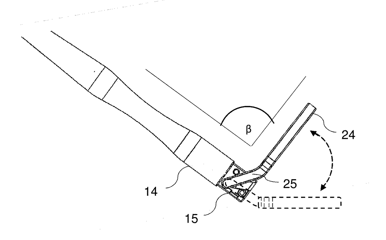
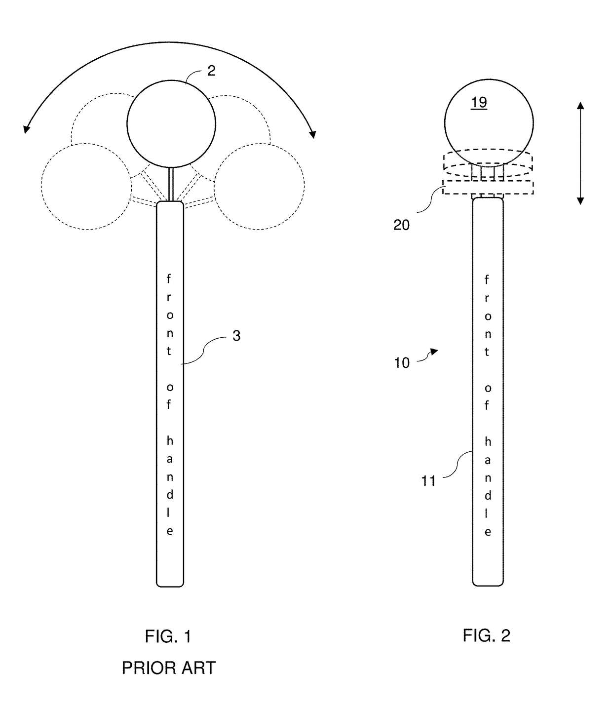
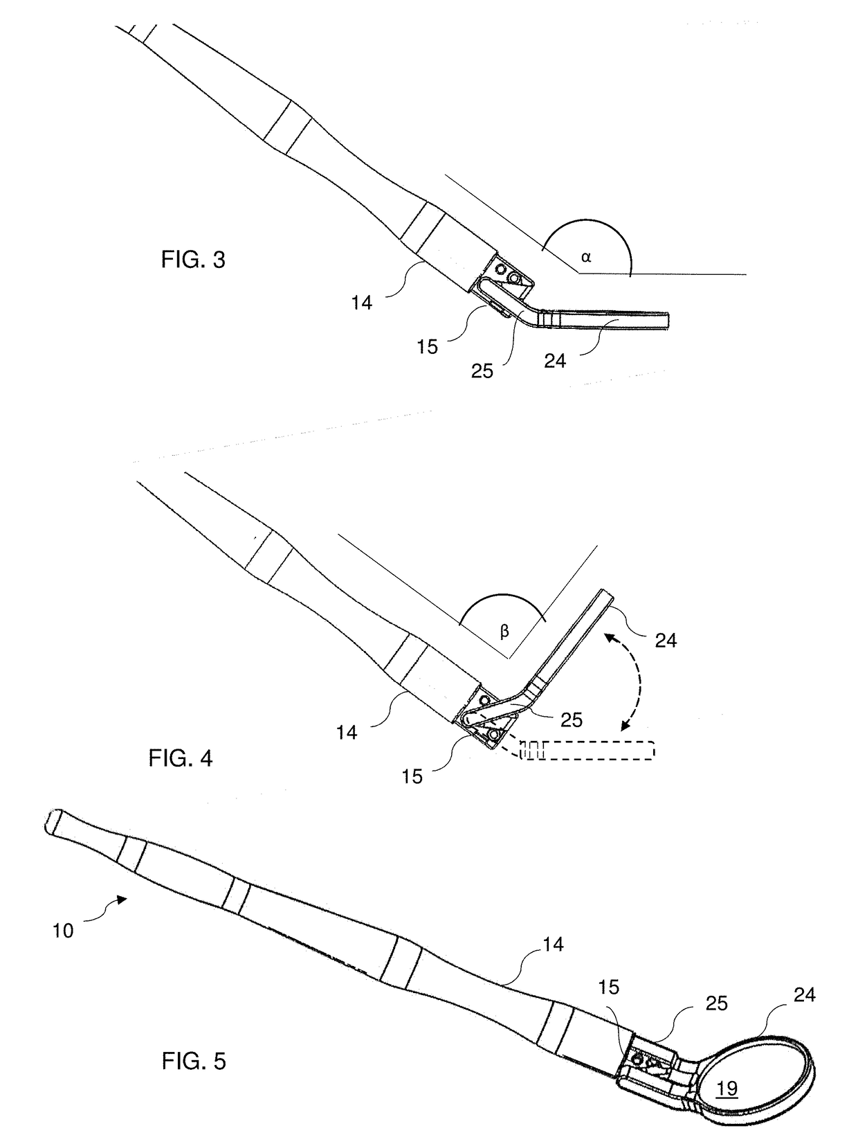
[0018]The present invention is an adjustable dental mirror designated generally as 10. FIG. 1 illustrates a prior art dental mirror in which the mirror 2 tilts side to side relative to the front of the handle 3, with the mirror face staying in the same plane relative to the handle. In contrast, FIG. 2 illustrates the present mirror 10 in which the mirror 20 moves from a first angle to a second angle relative to the front of the handle 11, moving the face 19 of the mirror out of the plane of the handle 11.

[0019]In the preferred embodiment, the dental mirror comprises a handle 11, a mirror 20, and a mirror face 19. See FIG. 5. The handle 11 comprises a body 14 and a neck 15 at its distal end. Preferably the handle 11 is shaped to fit comfortably in the practitioner's hand, for example with a constant circular cross-section or with a varying circular or oval cross-sections resulting in a curved outer surface. Preferably the handle 11 is unibody, with the body and neck made of a single ...


PUM


Abstract

A dental mirror permits the mirror face to be flipped from a first angle to a second angle relative to the handle, while the tool is still in the patient's mouth. Mirror and handle connect at a pivot point that is spaced away from the handle's distal end. The neck of the mirror has a detent nub that mates with recesses in the neck of the handle for positioning and holding the mirror in place relative to the handle. The mirror can be shifted from one position to another by pushing or pulling the mirror against the patient's cheek while the mirror is still in the patient's mouth, as the nub slides from one recess to another. In one embodiment the mirror is flipped from a position 145 degrees relative to the handle to 90 degrees relative to the handle. Stops are incorporated to limit angular travel at either position.

Description

CROSS-REFERENCE TO RELATED APPLICATIONS[0001]This application claims the benefit of co-pending U.S. Provisional Application No. 62 / 429,857 filed Dec. 4, 2016.FIELD OF INVENTION[0002]This invention relates to dental devices used inside a patient's mouth. This invention relates particularly to an adjustable dental mirror.BACKGROUND[0003]Dental mirrors are used by dentists, dental hygienists, and other practitioners to allow indirect vision inside the mouth, reflect light onto desired surfaces, and retract soft tissue. Typically the mirror is at a fixed angle relative to the handle, which renders many positions ergonomically challenging and can lead to practitioner fatigue and unnecessarily long procedure times. Some dental mirrors purport to address these problems by enabling the mirror to tilt from side to side, but that mimics manual rotation of the tool in the patient's mouth and similarly leads to awkward positions for the practitioner.[0004]The challenge with existing dental mirr...

Claims


Application Information

Patent Timeline
IPC IPC(8): A61C3/00A61B1/247
CPCA61C3/00A61B1/247G02B5/08
Inventor HARLAN, LAURENCE
Owner ACUITY INNOVATION & DESIGN LLC
Why Eureka
Try Eureka