Eureka AIR delivers breakthrough ideas for toughest innovation challenges, trusted by R&D personnel around the world.

Foam dispensers

Active Publication Date: 2018-06-07
RIEKE PACKAGING SYST LTD
View PDF15 Cites 4 Cited by
  • Summary
  • Abstract
  • Description
  • Claims
  • Application Information

AI Technical Summary

Benefits of technology

[0046]Returning to the plunger head 31; a nylon foam-regulator mesh 54 is bonded over the discharge outlet 36. This is a convenient place for attaching mesh and produces good foaming results. Or, a discrete end insert, of the nozzle (not shown) can be used to trap a mesh in place instead of bonding. Another option is to install a mesh inside/under the head at the top of the stem 33, where it can easily be

Problems solved by technology

This is technically demanding and commercially important, because wet or non-uniform foams have low consumer acceptability.
These dispensers mix well-defined p

Method used


Image

  • Foam dispensers
  • Foam dispensers
  • Foam dispensers

Examples


Example

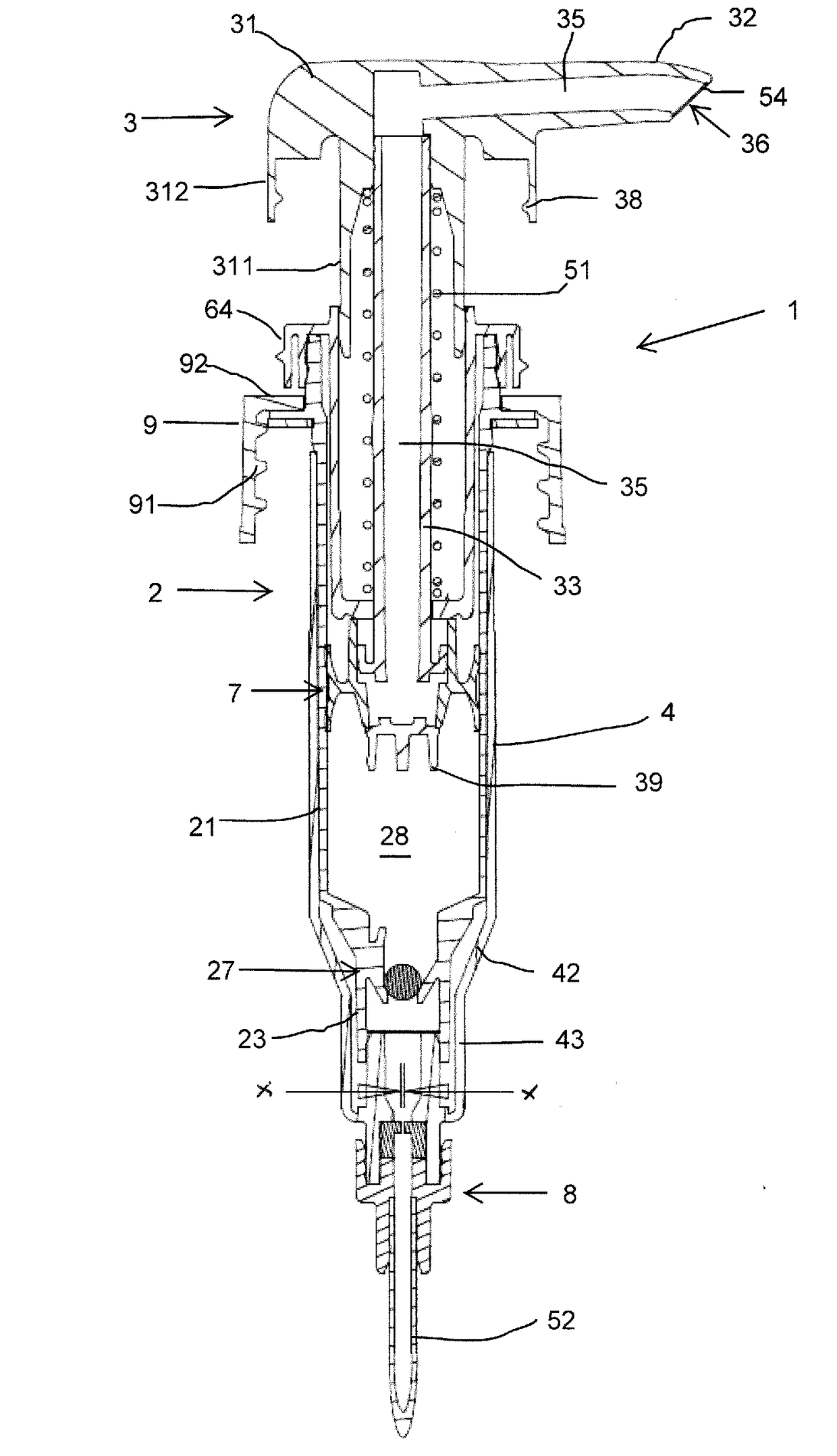
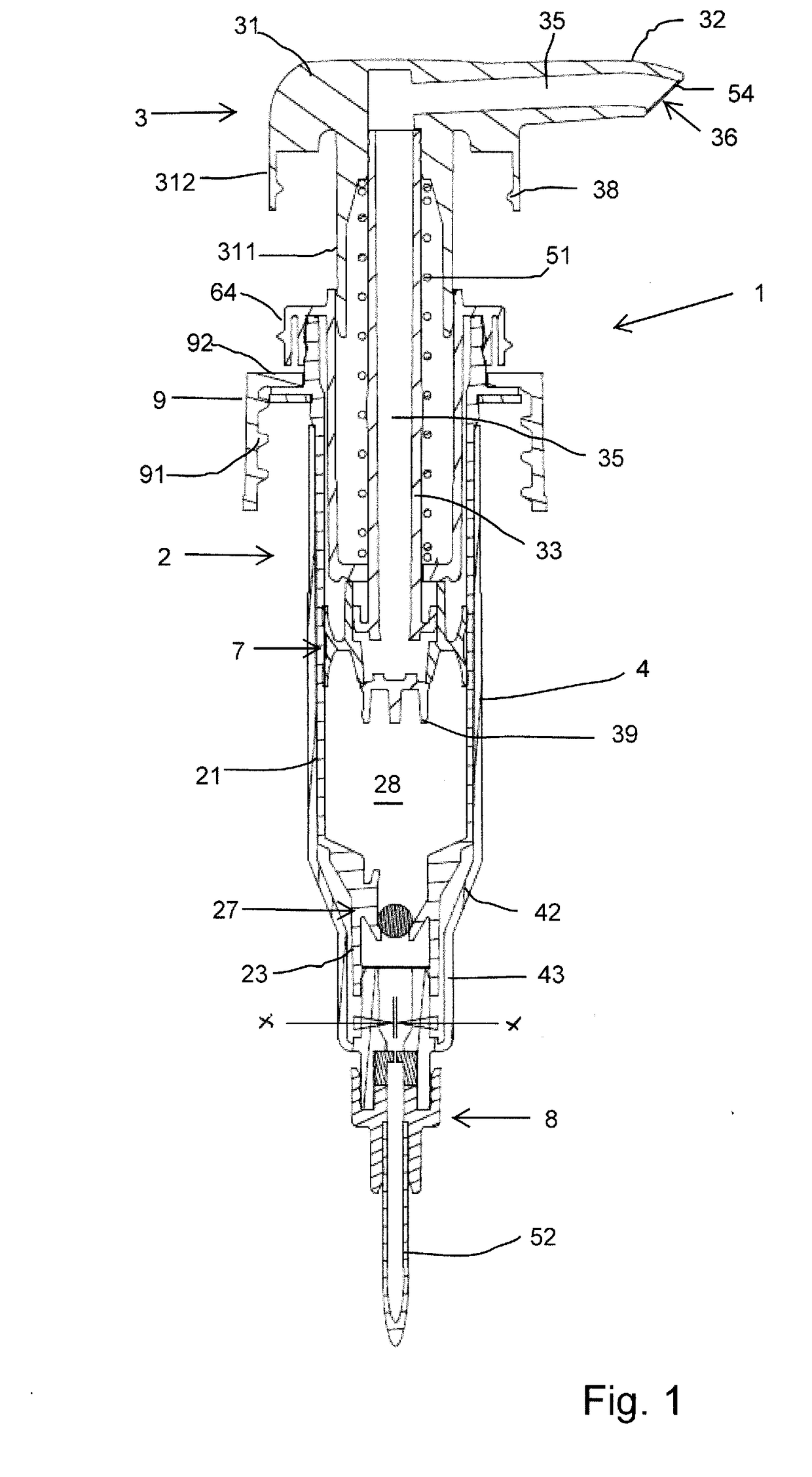
[0042]With reference to the drawing figures, a foam dispenser pump lf being an embodiment of the foam-generating device of our proposals, comprises generally a pump body 2 including a cylinder 21 defining a pump chamber 28 which is a foam chamber for the device and a plunger 3 mounted to reciprocate relative to the body 2, with a spring 51 acting between them and tending to push the plunger 3 up to the extended position shown in the figures. The body 2 is mounted in the threaded neck 101 of a container 100—shown fragmentarily in FIG. 3—by a closure cap 9 having internal threads 91 and a top inward flange 92, The pump body has an outward mounting flange 24 at the top of the cylinder which rests on the container neck 101 and is clamped against it by the cap flange 92 through a seal ring 11. See FIG. 6. Above the mounting flange 24 the body 2 has an upward tubular top projection 25 with snap formations on its outer surface.

[0043]A body insert 6, generally tubular in form, fits into the...


PUM


Abstract

A foam dispenser has a foam-generating pump (1) mounted on a container (100) to hold liquid. The pump (1) has a liquid intake conduit with a ball valve (27) and an air intake conduit (45) provided partly by a jacket component (4) fitting around the pump body (2) with clearance. The pump has structure defining a mixing zone (50) for mixing air and liquid, a foam chamber (28) for holding foam received from the mixing zone, and a discharge conduit leading from, the foam chamber to a discharge outlet (36). The mixed air and liquid pass through a permeable foam, regulator mesh (54), One or more air inlets (47) lead into the mixing zone (50) from the air intake conduit (45). A liquid inlet in the form of a restricted jet orifice (89) leads into the mixing zone (50) from the liquid intake conduit, upstream of the inlet ball valve (27). A regulator mesh (53) is also provided between the liquid inlet and mixing zone.

Description

[0001]This invention has to do with foam dispensers operable by hand; and particularly but not exclusively foam dispensers operable by a pumping action with reciprocation of a plunger.BACKGROUND[0002]Pump action hand foamers are well-known in the art. Generally they comprise a container for holding foamable liquid and a foam-generating device, typically comprising a plunger-operated pump, mounted in the neck of the container and having an inlet such as a dip tube communicating with the container interior to draw liquid into a pump chamber. To generate foam, the liquid must be mixed in appropriate proportion in air under turbulent conditions, with regulation as necessary to make the bubble size in the foam reasonably uniform. This is technically demanding and commercially important, because wet or non-uniform foams have low consumer acceptability.[0003]One well-established pump type has separate pump cylinders for the air and liquid, with respective inlet valves and pistons carried b...

Claims


Application Information

Patent Timeline
IPC IPC(8): B05B7/00B05B11/00
CPCB05B7/005B05B11/3087B05B11/3067B05B11/3073B05B11/3052B05B7/0037B05B11/1087B05B11/1098B05B11/1052B05B11/1067B05B11/1073
Inventor KNIGHT, SIMON CHRISTOPHER
Owner RIEKE PACKAGING SYST LTD
Why Eureka
Eureka Blog
Learn More