Eureka AIR delivers breakthrough ideas for toughest innovation challenges, trusted by R&D personnel around the world.

Travelling valve for a pumping apparatus

a technology of travelling valves and pumping apparatuses, which is applied in the direction of pump control, pump components, positive displacement liquid engines, etc., can solve the problems of irregular encounters, interrupting pumping operations, and not always perfectly centering

Inactive Publication Date: 2002-11-19
FORD MICHAEL BRENT
View PDF8 Cites 33 Cited by
  • Summary
  • Abstract
  • Description
  • Claims
  • Application Information

AI Technical Summary

Benefits of technology

will be apparent from the

Problems solved by technology

There are a number of problems that are regularly encountered during oil pumping operations.
This can be time-consuming and, of course, interrupts pumping operations.
Another problem is related to the ball and seat for the ball within the travelling valve.
However, because the travelling valve ball is not coupled to the seat, it does not always perfectly center when seating.
This can result in some leakage in the travelling valve and thus pumping inefficiency.
Moreover, improper seating can cause damage to both the ball and the seat, which are the shortest wear items in the oil pump.
Relatedly, while the seat can be inverted to extend its life, the constant rotation of the ball results in substantially even wear over the entire surface of the ball, making inversion to extend ball life impossible.
Still another problem is related to the impurities commonly found in the oil, such as sand.
Sand can become trapped between the side of the travelling valve and the interior wall of the oil pump.
When it becomes trapped in this manner, the constant up and down motion of the travelling valve can lead to scoring of the travelling valve, ultimately reducing its effectiveness and sometimes requiring its replacement.
Sand can also get between the ball and seat, preventing proper seating, possibly leading to damage and inefficiency.
Yet another problem is encountered during deviated or non-vertical pumping operations.
Where the oil pump is operating in a non-vertical orientation, the travelling valve ball will be pulled by gravitational forces toward the side of the travelling valve, preventing it from fully seating, potentially causing damage and inefficiency.
The pumping of heavy crude also presents problems.
This reduces pumping efficiency.

Method used


Image

  • Travelling valve for a pumping apparatus
  • Travelling valve for a pumping apparatus
  • Travelling valve for a pumping apparatus

Examples


Embodiment Construction

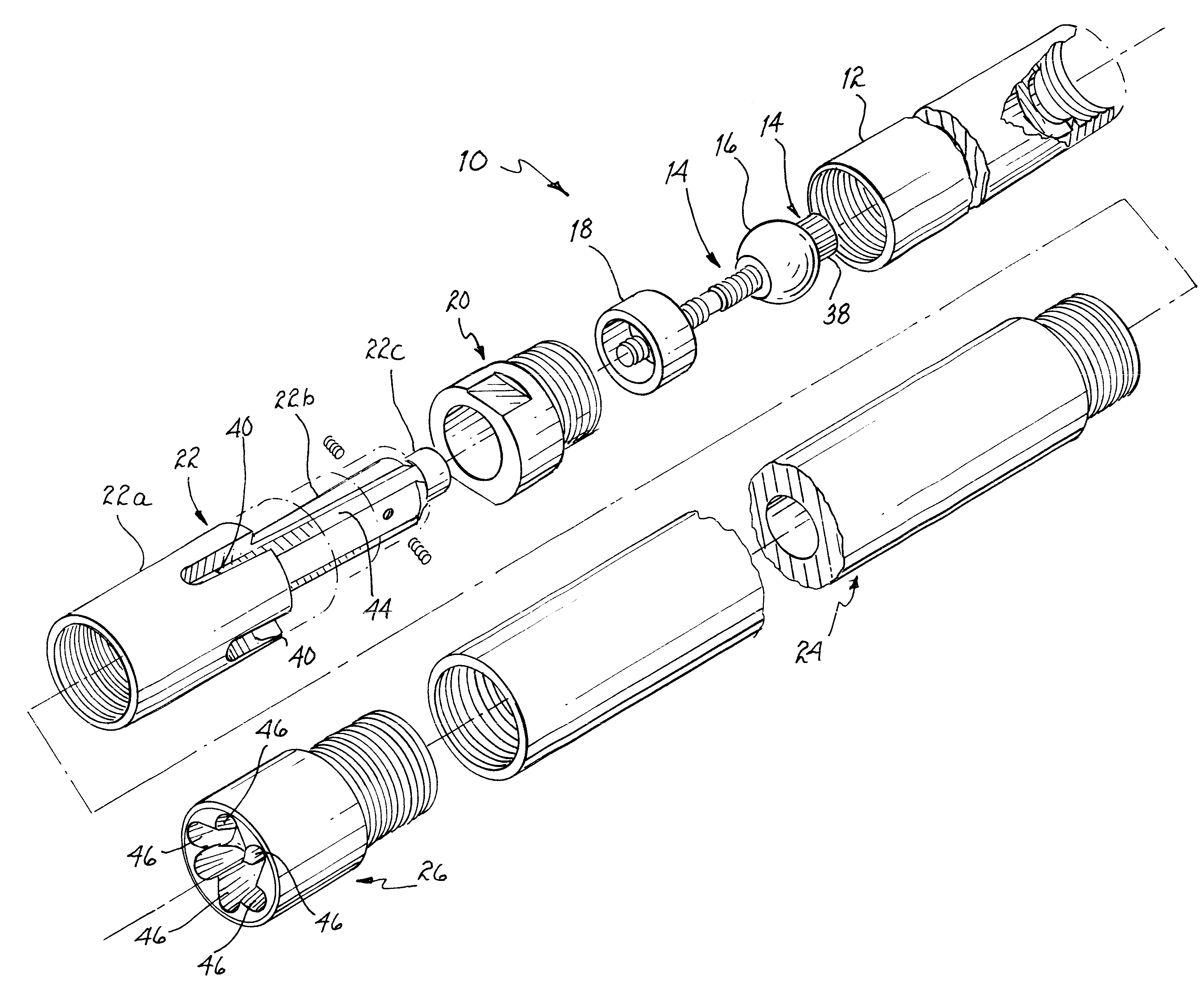
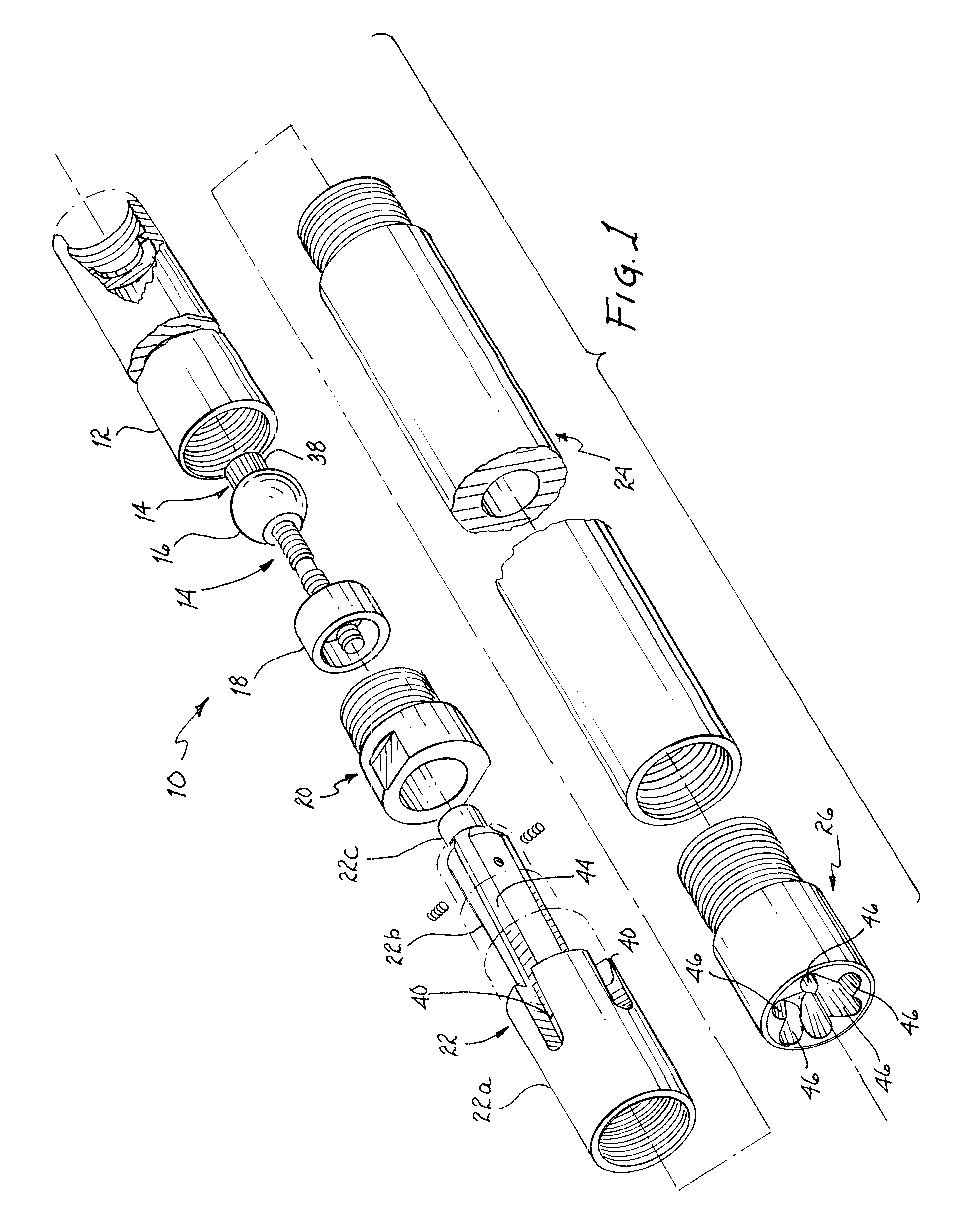
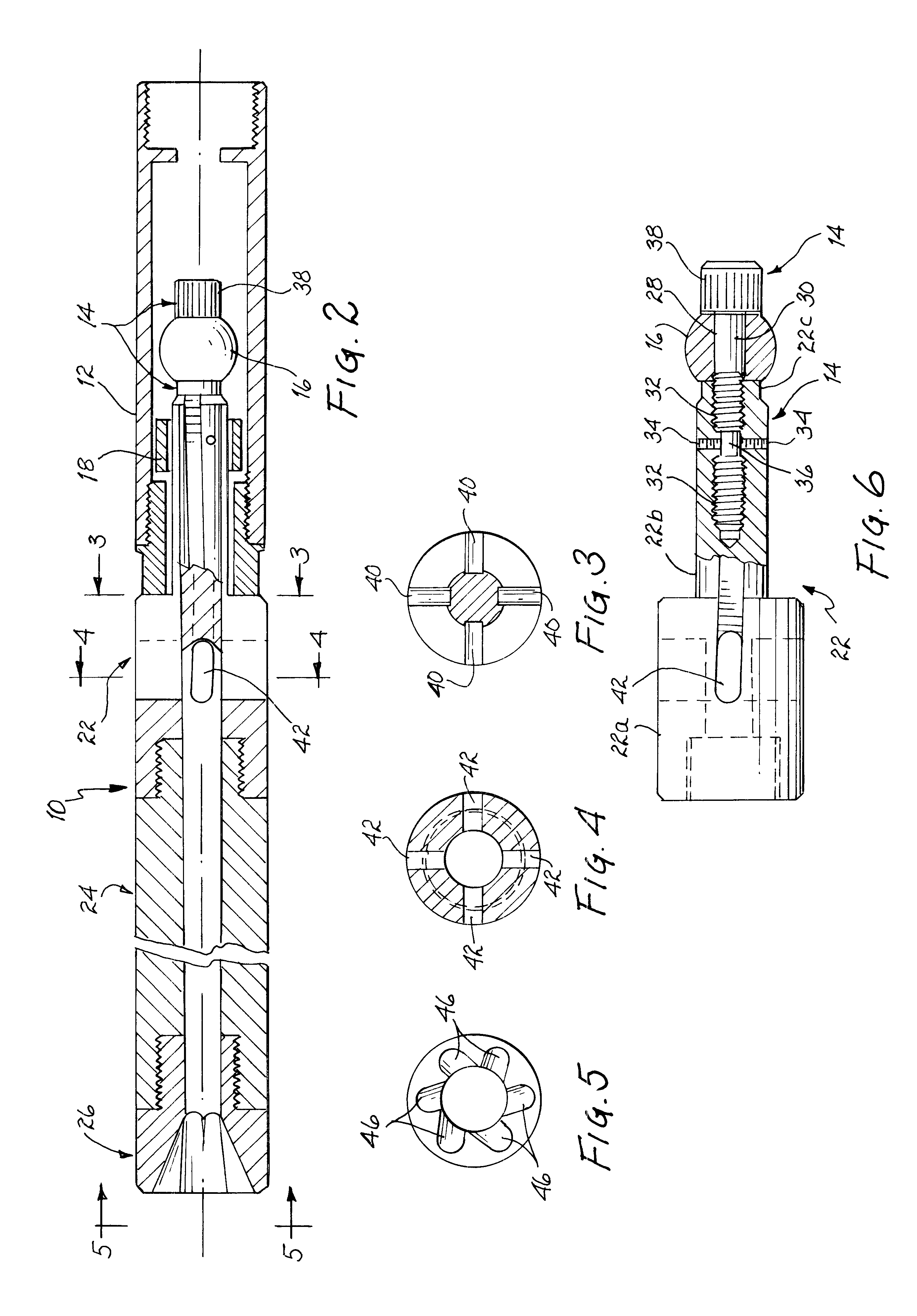
In accordance with one embodiment of the present invention, an improved travelling valve for use in a pumping apparatus is disclosed. The improved travelling valve comprises, in combination: a ball having a passage therethrough; a seal stem adapted to couple to the ball through the passage; an anchoring assembly adapted to anchor the ball to the seal stem; a seat positioned on the seal stem below the ball; and a drag plunger coupled at a first end thereof to the seal stem.

In accordance with another embodiment of the present invention, an improved travelling valve for use in a pumping apparatus is disclosed. The improved travelling valve comprises, in combination: a ball; a seat positioned below the ball; and means for imparting rotational movement to at least a portion of the improved travelling valve during pumping of fluid.

In accordance with another embodiment of the present invention, a method for pumping fluid is disclosed. The method comprises, in combination: providing a ball ...


PUM


Abstract

An improved travelling valve has a ball which is positioned on a seal stem, so that the ball is reliably centered when seated on the valve seat, reducing damage to the ball and seat from improper seating and providing increased efficiency for deviated or non-vertical pumping operations and the pumping of highly viscous fluids such as heavy crude. The improved travelling valve is constructed so that a lower portion of the valve rotates during pumping, and thereby imparts rotational movement to the fluid passed therethrough. Such rotational movement of the valve and fluid helps reduce gas lock, and reduces damage to the ball, seat, and valve exterior from impurities in the pumped fluid. Preferably, rotational movement is caused by angled channels in an interior portion of a vein rotator positioned at the bottom of the travelling valve, working in combination with angled channels in the seal stem.

Description

1. Field of InventionThis invention relates generally to oil pumps and travelling valves used therein, and more specifically, to an improved travelling valve providing benefits in the areas of gas lock prevention, wear resistance, and efficiency.2. Background of the InventionIn general terms, an oil well pumping system begins with an above-ground pumping unit, which creates the up and down pumping action that moves the oil (or other substance being pumped) out of the ground and into a flow line, from which the oil is taken to a storage tank or other such structure.Below ground, a shaft is lined with piping known as "tubing." Into the tubing is inserted a sucker rod, which is ultimately, indirectly, coupled at its north end to the pumping unit. The sucker rod is coupled at its south end, indirectly, to the oil pump itself, which is also located within the tubing, which is sealed at its base to the tubing. The sucker rod will couple to the oil pump at a coupling known as a 3-wing cage...

Claims


Application Information

Patent Timeline
IPC IPC(8): F04B53/10F04B47/02F04B53/12F04B47/00
CPCF04B47/02F04B53/125
Inventor FORD, MICHAEL BRENT
Owner FORD MICHAEL BRENT
Why Eureka
Eureka Blog
Learn More