System and method for high efficiency power generation using a carbon dioxide circulating working fluid

a working fluid and high efficiency technology, applied in the field of high efficiency power generation using a working fluid with circulating carbon dioxide, can solve the problem that the system can exceed such efficiency, and achieve the effect of high efficiency

Active Publication Date: 2011-07-28
8 RIVERS CAPTTAL LLC
View PDF100 Cites 254 Cited by
  • Summary
  • Abstract
  • Description
  • Claims
  • Application Information

AI Technical Summary

Benefits of technology

[0005]The present invention provides methods and system for power generation using a high efficiency combustor (e.g., a transpiration cooled combustor) in combination with a circulating fluid (e.g., a CO2 circulating fluid). In particular, the circulating fluid can be introduced into the combustor along with a fuel and an oxidant for combustion such that a high pressure, high temperature fluid stream is produced comprising the circulating fluid and any combustion products. The fluid stream can be introduced into a power generation device, such as a turbine. Advantageously, the fluid stream can be maintained at a relatively high pressure during expansion in the turbine such that the pressure ratio across the turbine (i.e., the ratio of the pressure at the turbine inlet and the pressure at the turbine outlet) is less than about 12. The fluid stream can then be further processed for separation of the components of the fluid stream, which can include passing the fluid stream through a heat exchanger. In particular, the circulating fluid (at least a portion of which may be recycled from the fluid stream) can be passed through the same heat exchanger to heat the circulating fluid prior to introduction into the combustor. In such embodiments, it may be useful to operate the heat exchanger (e.g., through selection of a low grade heat source) such that heat exchanger has only a small temperature difference between the turbine exhaust and the recycle fluid at the hot end of the heat exchanger.
[0006]In certain aspects, the invention provides power production systems that can produce power at high efficiency with low capital cost and also can produce substantially pure CO2 at pipeline pressure for sequestration. The CO2 also may be recycled into the power production system.

Problems solved by technology

The present system can exceed such efficiency while also delivering CO2 for sequestration or other disposal at required pressures.

Method used


Image

  • System and method for high efficiency power generation using a carbon dioxide circulating working fluid
  • System and method for high efficiency power generation using a carbon dioxide circulating working fluid
  • System and method for high efficiency power generation using a carbon dioxide circulating working fluid

Examples


example 1

System and Method for Power Production with Methane Combustion Using a Recycled CO2 Circulating Fluid

[0255]One specific example of a system and method according to the present invention is illustrated in FIG. 11. The following description describes the system in relation to a specific cycle under specific conditions using computer modeling.

[0256]In this model, a methane (CH4) fuel stream 254 at a temperature of 134° C. and a pressure of 30.5 MPa is combined with a recycled CO2 circulating fluid stream 236 at a temperature of 860° C. and a pressure of 30.3 MPa (and thus in a supercritical fluid state) in a mixer 252 prior to introduction into a transpiration cooled combustor 220. An air separation unit 30 is used to provide concentrated O2 242 at a temperature of 105° C. and a pressure of 30.5 MPa. The air separation unit also produces heat (Q) that is drawn off for use in the process. The O2 242 is combined in the combustor 220 with the methane fuel stream 254 and the CO2 circulatin...

example 2

System and Method for Power Production with a Pulverized Coal Power Station Retrofit to Use a Recycled CO2 Circulating Fluid

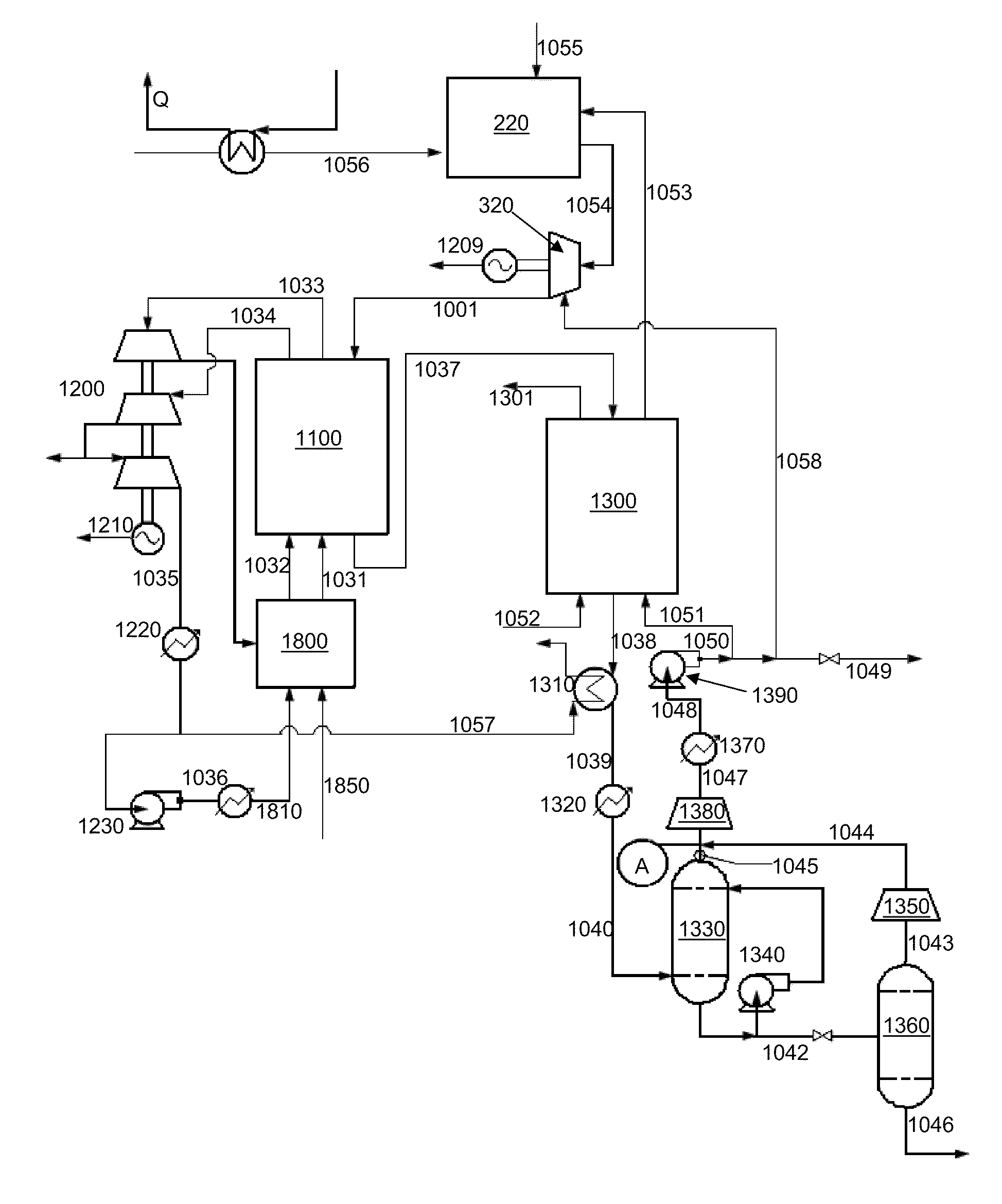
[0263]Another specific example of a system and method according to the present invention is illustrated in FIG. 12. The following description describes the system in relation to a specific cycle under specific conditions using mathematical modeling.

[0264]In this model, the ability to retrofit a system and method as described herein to a conventional pulverized coal fired power station is illustrated.

[0265]An O2 stream 1056 at a pressure 30.5 MPa is introduced into a transpiration cooled combustor 220 along with a carbon containing fuel 1055 (e.g., coal-derived gas produced by partial oxidation) at a pressure of 30.5 MPa and a CO2 circulating fluid stream 1053 at a pressure of 30.5 MPa. The O2 may be received from an air separator or similar device that can produce heat (Q), which can be drawn off for use in the system, such as to produce steam for expansion or ...


PUM


Abstract

The present invention provides methods and system for power generation using a high efficiency combustor in combination with a CO2 circulating fluid. The methods and systems advantageously can make use of a low pressure ratio power turbine and an economizer heat exchanger in specific embodiments. Additional low grade heat from an external source can be used to provide part of an amount of heat needed for heating the recycle CO2 circulating fluid. Fuel derived CO2 can be captured and delivered at pipeline pressure. Other impurities can be captured.

Description

CROSS-REFERENCE TO RELATED APPLICATIONS[0001]The present patent application claims priority to U.S. Provisional Patent Application No. 61 / 299,272, filed Jan. 28, 2010, and U.S. patent application Ser. No. 12 / 714,074, filed Feb. 26, 2010, which claims priority to U.S. Provisional Patent Application No. 61 / 155,755, filed Feb. 26, 2009, the disclosures of which are incorporated herein by reference in their entirety.FIELD OF THE INVENTION[0002]The present invention is directed to systems and methods for generation of power, such as electricity, through use of a circulating fluid to transfer energy generated through high efficiency combustion of a fuel. Particularly, the system and method can use carbon dioxide as the circulating fluid.BACKGROUND OF THE INVENTION[0003]It is estimated that fossil fuels will continue to provide the bulk of the world's electric power requirements for the next 100 years while non-carbon power sources are developed and deployed. Known methods of power generat...

Claims


Application Information

Patent Timeline
Patent Type & Authority Applications(United States)
IPC IPC(8): F02C3/20F23D1/00F23L7/00
CPCF23L2900/07002F01K3/186F23M5/085F23M2900/05004Y02E20/322Y02E20/344F01K13/00F01K25/103F02C3/22F02C3/34F05D2260/61F22B35/12F23L7/007F23L2900/07001F25J3/04533F25J3/04618F25J2230/06F25J2240/70F25J2240/82F25J2260/80F02C3/20F01K23/10F02C7/00F01K3/185F23M5/00F01K25/10F25J3/04018F25J3/04545Y02E20/32Y02E20/34F02C3/04
Inventor ALLAM, RODNEY JOHNPALMER, MILESBROWN, JR., GLENN WILLIAM
Owner 8 RIVERS CAPTTAL LLC
Why Eureka
Try Eureka