Wheel suspension system

a technology of suspension system and wheel, which is applied in the direction of suspension arms with a strong grip, vehicle components, and suspensions that are resilient, can solve the problems of complex kinematics of chassis, and achieve the effect of small installation space requirements

Active Publication Date: 2018-06-07
ZF FRIEDRICHSHAFEN AG
View PDF0 Cites 10 Cited by
  • Summary
  • Abstract
  • Description
  • Claims
  • Application Information

AI Technical Summary

Benefits of technology

[0016]With the arrangement of the steering gear in a plane with the first transverse link and with the arrangement of the section of the steering gear between the ends of the first transverse link stud of the first transverse control on the chassis side and the end of the second transverse link stud of the first transverse link on the chassis side, it is possible, in contrast to a conventional wheel suspension, to efficiently and optimally utilize the installation space available for the wheel suspension assembly. In contrast to a conventional wheel suspension, installation space is advantageously saved with the wheel suspension assembly according to the present invention. The entire upper plane of the transverse link may thus be constructed more compactly than in a conventional wheel suspension, without having to accept losses relating to axial kinetics, stability or functionality of the wheel suspension.
[0021]Thus, the shape of the reversing lever conforms on the one hand to the suspension range of the first transverse link and to the steering range of the hub carrier, and on the other hand the shape of the reversing lever conforms to the shape of the hub carrier in the section that shares a plane with the reversing lever, and to the shape of the first transverse in the section that shares a plane with the reversing lever. The form of the steering range naturally also conforms to the shape of the hub carrier. The form of the suspension range naturally also conforms to the shape of the first transverse link. Thus, the reversing lever is designed in such a way that no collisions of the reversing lever with the hub carrier and / or with the first transverse link and / or with additional components of the wheel suspension assembly occur, either in the design attitude or in a vehicle operating state. This adapted shape of the reversing lever enables a more compact construction and saves installation space, as compared to a conventional wheel suspension assembly. Thus, the available installation space is efficiently utilized.
[0027]The web of the second transverse link extends from the kinematics point of the second transverse link on the hub carrier side to the attachment point of the second transverse link, by means of which the pendulum support is connected to the second transverse link. The web of the second transverse link is designed narrower and longer than an end of a conventional transverse link on the hub carrier side. As a result, the transverse link assumes a Y-shape. However, this design does not impair the stability and the functionality of the second transverse link.
[0028]According to another embodiment, the shape of the web of the second transverse link is defined by the steering range of the hub carrier. The shape may also be defined by a pivot range of a wheel, which is connected to the hub carrier when the wheel suspension assembly is used in a vehicle. The web may, for example, taper close to the hub carrier, to prevent the hub carrier from colliding with the web of the second transverse link when a maximum steering turning angle is adopted.
[0033]The curvature is designed in such a way with respect to an available installation space for the wheel suspension assembly that no conflicts, for example, collisions, occur with other components of the wheel suspension assembly, neither in design attitude nor in a vehicle operating state. Moreover, the curvature does not result in losses with respect to component stability and component kinematics of the transverse link. The curvature is designed in such a way that a material-free area is created, through which additional components of the wheel suspension assembly may be guided. In this case, it is advantageous that the transverse link and at least one additional component of the wheel suspension assembly of the vehicle may be spatially closely arranged, resulting in a smaller installation space requirement than in a first transverse link having a completely planar design.

Problems solved by technology

In the case of wheel suspensions for novel mobility concepts which, for example, enable steering angles of at least + / −50° up to + / −90°, the chassis kinematics becomes more complex compared to conventional axle assemblies having maximum steering angles of + / −50°, because additional components are required.

Method used


Image

  • Wheel suspension system
  • Wheel suspension system

Examples


Embodiment Construction

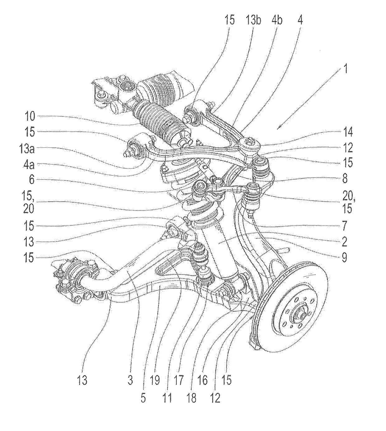
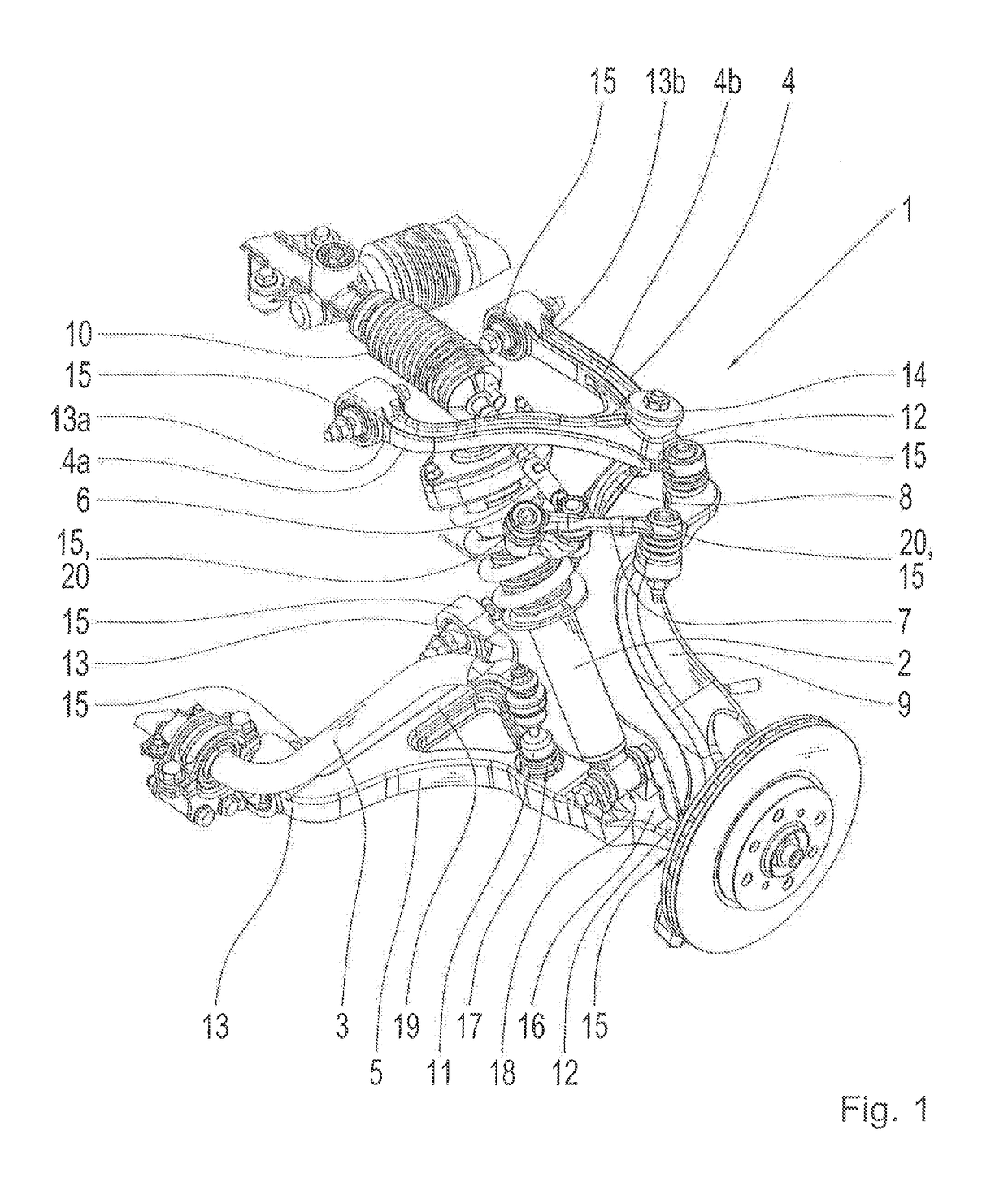
[0036]The FIGURE shows a schematic representation of a wheel suspension assembly 1 according to one exemplary embodiment. The wheel suspension assembly 1 has the following components: a spring damper 2, a stabilizer bar 3, a first transverse link 4, a second transverse link 5, a first fie rod 6, a second tie rod 7, a reversing lever 8, a hub carrier 9 and steering gear 10 and a pendulum support 11. The wheel suspension assembly 1 is shown in the design configuration.

[0037]The first transverse link 4 is shaped as a triangular transverse link and is the upper transverse link. The first transverse link 4 has a first transverse link strut 4a and a second transverse link strut 4b. In addition, the first transverse link has a hub carrier end 12 and two ends 13a, 13b on the chassis side. The first transverse link strut 4a of the first transverse link 4 is delimited by the the hub carrier end 12 and by one of the ends 13a on the chassis side. The second transverse link strut 4b of the first...


PUM


Abstract

A wheel suspension assembly (1) for a vehicle, having a spring damper (2), a first transverse link (4), which has a first transverse link strut (4a) and a second transverse link strut (4b), a second transverse link (5), a first tie rod (6), a second tie rod (7), a reversing lever (8), a hub carrier (9), a steering gear (10) and a pendulum support (11). Each transverse link (4, 5) has an end (12), on the hub carrier side, and two ends (13, 13a, 13b), on the chassis side. The steering gear (10) is arranged in a plane with the first transverse link (4) and in a section between an end (13a) of the first transverse link strut (41) of the first transverse link (4), on the chassis side, and an end (13b) of the second transverse link strut (4b) of the first transverse link (4), on the chassis side.

Description

[0001]This application is a National Stage completion of PCT / EP2016 / 059153 filed Apr. 25, 2016, which claims priority from German patent application serial no. 10 2015 209 844.3 filed May 28, 2015.FIELD OF THE INVENTION[0002]The present invention relates to a wheel suspension assembly for a vehicle.BACKGROUND OF THE INVENTION[0003]In the case of wheel suspensions for novel mobility concepts which, for example, enable steering angles of at least + / −50° up to + / −90°, the chassis kinematics becomes more complex compared to conventional axle assemblies having maximum steering angles of + / −50°, because additional components are required. In spite of the additional components in the wheel suspension, the installation space available for the wheel suspension remains the same. Frequently, a volume of installation space for the wheel suspension is defined, which may not be exceeded. Thus, an effective and optimized utilization of the available installation space is obligatory.[0004]A wheel s...

Claims


Application Information

Patent Timeline
Patent Type & Authority Applications(United States)
IPC IPC(8): B60G3/20B60G7/00B62D7/20B62D7/06
CPCB60G3/20B60G7/008B62D7/06B62D7/20B60G2200/44B60G2204/143B60G2206/11B60G2206/12B60G2206/124B60G2204/422B60G2206/427B60G2200/144
Inventor NEU, ALEXANDERHEIDSIECK, KNUTKONTERMANN, PETERLOHMULLER, HOLGERKNAUB, WITALIJCICHY, JOACHIMSOLIK, KLAUS
Owner ZF FRIEDRICHSHAFEN AG
Why Eureka
Try Eureka