Shock absorbing disruptor mounting system

a technology of disruptors and mounting systems, applied in the direction of gripping heads, manipulators, weapons, etc., can solve the problems of disruptor devices, requiring explosive ordinance disposal personnel to be in dangerous proximity, and inability to detonate, so as to facilitate the travel of the thrust sleeve

Active Publication Date: 2018-06-07
HARRIS CORP
View PDF0 Cites 1 Cited by
  • Summary
  • Abstract
  • Description
  • Claims
  • Application Information

AI Technical Summary

Benefits of technology

[0007]A motor is configured to urge the carriage in a first direction along a length of the linear guide structure. The motor includes an actuator which is configured to selectively decouple from an engagement with the carriage responsive to the disruptor force. The actuator is comprised of an elongated slider which selectively applies a force to a thrust bearing face of a thrust sleeve disposed on the carriage responsive to the operation of the motor. The elongated slider extends through an aperture defined in thrust bearing face. The aperture facilitates travel of the thrust sleeve along a length of the elongated slider responsive to the disruptor force. A spring element is provided to urge the carriage in a second direction opposed from the first direction.

Problems solved by technology

Projected water disruptors utilize a charge-propelled water projectile to destroy explosive ordnance by rapidly separating the components of the explosive device, rendering it unable to detonate.
One limitation of such disruptor devices is that they need to be positioned in close proximity to the explosive ordinance in order to be effective.
This can require explosive ordinance disposal (EOD) personnel to be in dangerous proximity to the explosive ordinance.
For example, high impulse loads associated with disruptors have the potential to damage the robot or its manipulator arm.
As threats become harder to deal with, EOD personnel deploy higher power disruptor devices which increase the potential for damaging the URV.

Method used


Image

  • Shock absorbing disruptor mounting system
  • Shock absorbing disruptor mounting system
  • Shock absorbing disruptor mounting system

Examples


Embodiment Construction

[0015]It will be readily understood that the components of the embodiments as generally described herein and illustrated in the appended figures could be arranged and designed in a wide variety of different configurations. Thus, the following more detailed description of various embodiments, as represented in the figures, is not intended to limit the scope of the present disclosure, but is merely representative of various embodiments. While the various aspects of the embodiments are presented in drawings, the drawings are not necessarily drawn to scale unless specifically indicated.

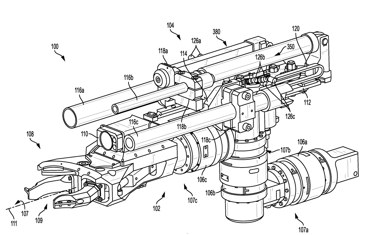
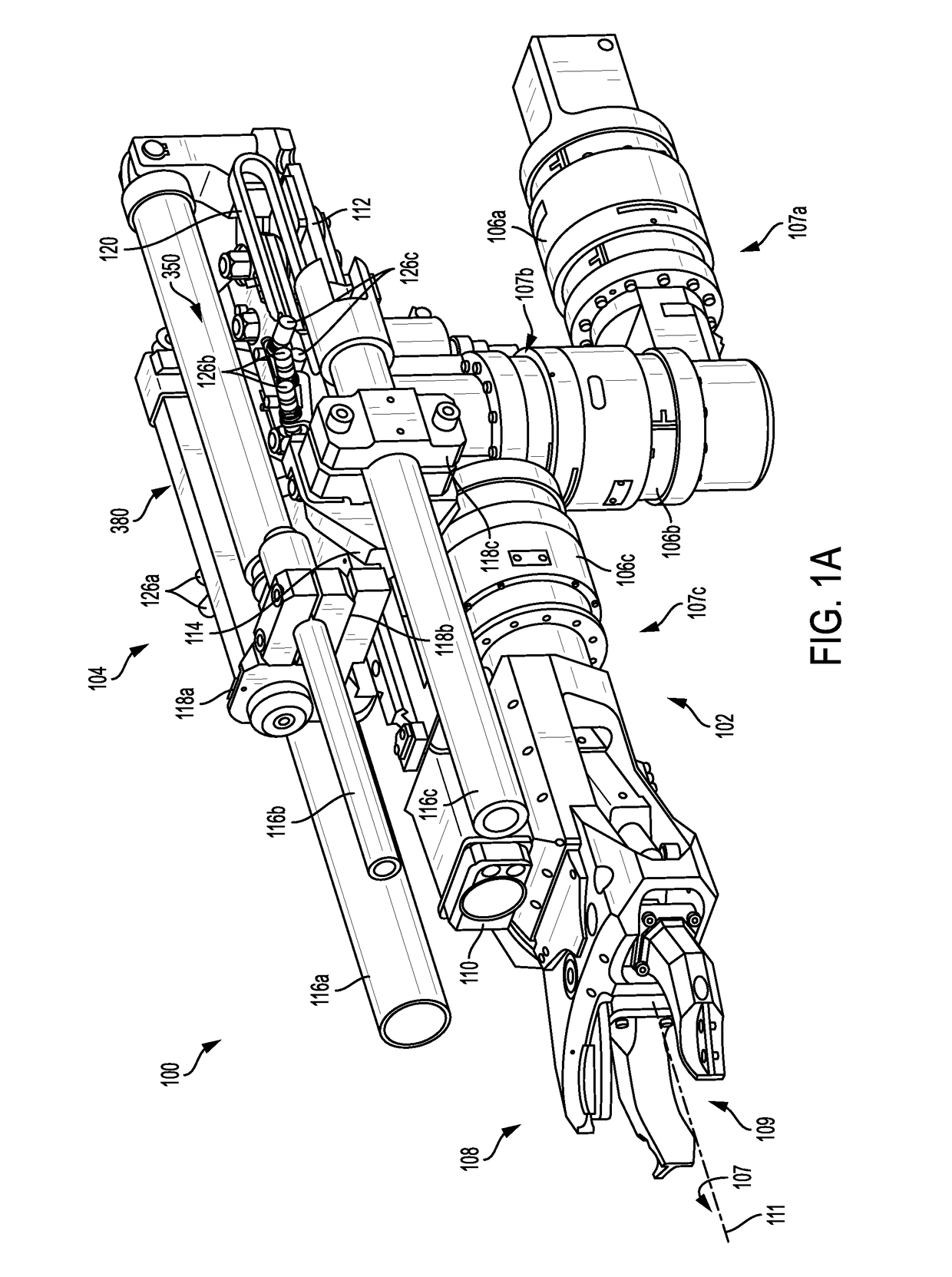
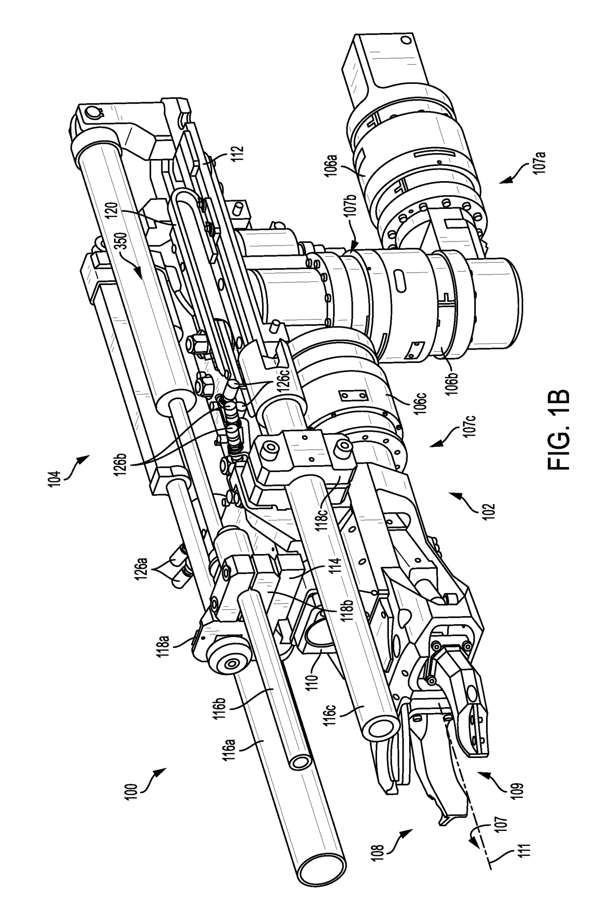
[0016]A disruptor can be mounted to a robotic manipulator arm of an unmanned robotic vehicle (URV). But high impulse loads associated with disruptors have the potential to damage the robot or its manipulator arm. As threats become harder to deal with, explosive ordinance disposal (EOD) personnel deploy higher power disruptor devices which increase the potential for damaging the URV.

[0017]Embodiments discl...


PUM


Abstract

A shock absorbing disruptor mounting system for a robotic arm includes a rack comprised of a linear guide structure and a carriage which is configured to travel on the linear guide structure. The carriage is selectively movable between a retracted position and an extended position and includes a plurality of wheels along its length. Each of the wheels has a wheel axis of rotation which is transverse to the direction of the linear guide structure centerline to facilitate rotation of the wheels on at least a portion of the linear guide structure responsive to the travel.

Description

BACKGROUNDStatement of the Technical Field[0001]The technical field of this disclosure comprises systems and methods for defeating explosive ordinance and more particularly concerns systems and methods for deploying disruptor devices using unmanned robotic vehicles.Description of the Related Art[0002]Projected water disruptors utilize a charge-propelled water projectile to destroy explosive ordnance by rapidly separating the components of the explosive device, rendering it unable to detonate. One limitation of such disruptor devices is that they need to be positioned in close proximity to the explosive ordinance in order to be effective. This can require explosive ordinance disposal (EOD) personnel to be in dangerous proximity to the explosive ordinance. Accordingly, an unmanned robotic vehicle (URV) can be used in place of a person to position the disruptor. For example, a disruptor can be mounted on a robotic manipulator arm of the URV to facilitate the positioning of the disrupto...

Claims


Application Information

Patent Timeline
Patent Type & Authority Applications(United States)
IPC IPC(8): F41A25/18
CPCF41A25/18B25J11/0025B25J15/00B25J19/0091F41A25/00F41A25/22F41A25/24
Inventor BOWMAN, MICHAEL E.SUMMER, MATTHEW D.BOSSCHER, PAUL M.
Owner HARRIS CORP
Why Eureka
Try Eureka