Razor blade assembly

Inactive Publication Date: 2018-06-14
DEPAZ AMIR
View PDF6 Cites 9 Cited by
  • Summary
  • Abstract
  • Description
  • Claims
  • Application Information

AI Technical Summary

Benefits of technology

[0030]In again another embodiment the first and second razor blades comprise tabs or wings arranged at the small sides of the first and second razor blades. Therewith the advantage can

Problems solved by technology

A drawback of these known razor blades is that they must be very thin and that due to the holes in the thin metal sheets for receiving the threaded pin and the locating pins the razor blades have an un-homogeneous resistanc

Method used


Image

  • Razor blade assembly
  • Razor blade assembly
  • Razor blade assembly

Examples


first embodiment

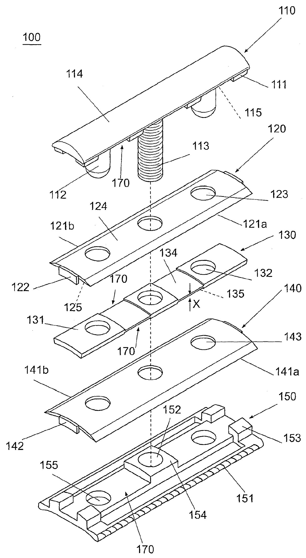
[0052]FIGS. 1-9 illustrate the razor blade assembly 100 according to the invention which comprises at least an upper plate 110, a first razor blade 120, a spacer member 130, a second razor blade 140 and a bottom plate 150.

[0053]The upper plate 110 comprises a curved upper surface 114, two guide posts 112 spaced on the ends of the plate and a center threaded post 113. The center threaded post 113 is designed to thread into a complementary receptacle 161 in the handle 160 (FIG. 5). The lower surface 115 of the upper plate 110 is also curved but has a greater radius than the curve of the upper surface 114. Attached to the lower surface 115 are multiple spacers 111 which are generally square or rectangular in shape. The multiple spacers 111 are positioned at least on the corners of the upper plate 110 and approximately ⅓ the distance of the length of the plate in from the opposing ends of the upper plate 110. The spacers 111 provide a space between the lower surface 115 of the upper pla...

second embodiment

[0075]FIG. 10 illustrates the razor blade assembly 100 according to the invention which differs from the embodiment of FIGS. 1-9 only therein that the handles in the form of tabs or wings 122, 142 of the first and second razor blades 120, 140 are shaped differently, namely the tabs or wings 122, 142 are rounded and flattened outwards.

third embodiment

[0076]FIGS. 11-13 illustrate the razor blade assembly 100 according to the invention which differs from the embodiment of FIGS. 1-9 only therein that the long sides of the lower portion of the lower plate 150 comprise recesses 156 that are equally spaced along the long sides so as to form an open comb.

[0077]Although the invention has been described in conjunction with specific embodiments thereof, it is evident that many alternatives, modifications and variations will be apparent to those skilled in the art. Accordingly, it is intended to embrace all such alternatives, modifications and variations that fall within the scope of the appended claims.

[0078]It is appreciated that certain features of the invention, which are, for clarity, described in the context of separate embodiments, may also be provided in combination in a single embodiment. Conversely, various features of the invention, which are, for brevity, described in the context of a single embodiment, may also be provided sep...


PUM


Abstract

Razor blade assembly (100), comprising in sequence an upper plate (110) with a radius of curvature RU; a first razor blade (120) of the thickness T1; a curved spacer member (130) with a radius of curvature RS; a second razor blade (140) of the thickness T2; and a lower plate (150) having a radius of curvature RL, wherein these elements can be reversibly assembled and mounted vertically in height on a razor handle (160); the first razor blade (120) and the second razor blade (140) have a generally rectangular shape and comprise a front cutting edge (121a, 141a) and a rear cutting edge (121b, 141b) running lengthwise; the first and second razor blades (120,140) in its unloaded state are curved in a cross-sectional plane orthogonal to the cutting edges; and the thickness T1 and T2 of the first and second razor blades (120,140) is at least 0.45 mm, and preferably at least 0.50 mm.

Description

BACKGROUND OF THE INVENTION1. Field of the Invention[0001]The invention relates to a razor blade assembly according to the preamble of claim 1 and to a razor blade for a razor blade assembly according to the preamble of claim 18.2. Description of the Related Art[0002]A conventional razor blade assembly is known from U.S. Pat. No. 2,713,201 PLESCH. This known assembly comprises an upper clamping plate of curved cross-section, a first razor blade, an intermediate plate of curved cross-section, a second razor blade, a lower clamping plate of curved cross-section and a handle. The upper clamping plate has a central threaded pin and two locating pins arranged laterally of the threaded pin, wherein the threaded pin and the locating pins extend through each a set of corresponding holes formed in the first and second razor blades, the intermediate plate and the lower clamping plate.[0003]The razor blades are planar thin metal sheets which are bent to their curved state by means of the curve...

Claims


Application Information

Patent Timeline
IPC IPC(8): B26B21/56B26B21/22B26B21/40B26B21/52
CPCB26B21/565B26B21/22B26B21/4012B26B21/521B26B21/4068B26B21/18B26B21/56
Inventor DEPAZ, AMIR
Owner DEPAZ AMIR
Why Eureka
Try Eureka