Noise Dampening Brake Shoe for a Drum Brake

a drum brake and noise dampening technology, which is applied in the direction of noise/vibration control, braking elements, braking members, etc., can solve the problems of warranty claims, noise is unpleasant and distracting the driver of the vehicle, and the brake shoe resonance is reduced, so as to reduce the noise of the brake sho

Active Publication Date: 2018-06-14
BENDIKS SPAJSER FAUNDEJSHN BREJK LLK
View PDF0 Cites 0 Cited by
  • Summary
  • Abstract
  • Description
  • Claims
  • Application Information

AI Technical Summary

Benefits of technology

[0006]This invention relates to vehicle brakes. In particular, the invention relates to a brake shoe for a drum brake assembly that is configured to reduce resonance of the brake shoe during engagement of the brake to reduce brake noise.
[0009]A brake shoe for a drum brake in accordance with another embodiment of the invention includes a brake table and a web supporting the brake table and having first and second ends. The first end is configured for pivotally coupling to an associated brake spider of the drum brake and the second end is configured to respond to a force applied by an actuator that causes the brake shoe to move between positions of engagement and disengagement with an associated braking surface. The brake shoe further includes a damping plate disposed on a first side of the web and coupled to the web. The damping plate is configured to, during engagement of the brake shoe with the associated braking surface, dampen movement of the brake shoe for a natural frequency of the brake shoe having an order of at least two and a causing a bending modal shape of the brake shoe.
[0011]A brake shoe for a drum brake in accordance with the invention represents an improvement as compared to conventional brake shoes. As noted hereinabove, conventional drum brake assemblies emit a low frequency noise or squeal during application of the brakes when the brake shoes engage the braking surface of the drum. It has been determined that this noise results, in part, from a resonance of natural frequencies in the brake drum, brake shoes and other brake components and, in particular, resonance at certain natural frequencies that generate bending modal shapes in the brake shoes. The inventors herein have developed a configuration of a brake shoe that reduces resonance and modal and operating deflection shapes of the brake shoe by dampening movement of the brake shoe for second order or grater natural frequencies of the brake shoe that cause bending modal shapes of the brake shoe. As a result, the inventive brake shoe reduces the typical squeal that occurs during engagement of the brake.

Problems solved by technology

The noise occurs when multiple components in the brake resonate at a common natural frequency or multiple thereof.
This noise is unpleasant and distracting to the driver of the vehicle from which the noise emanates and to others within the audible range of the noise including drivers in surrounding vehicles.
The noise can also result in warranty claims by vehicle owners asserting that the brake is not functioning properly.

Method used


Image

  • Noise Dampening Brake Shoe for a Drum Brake
  • Noise Dampening Brake Shoe for a Drum Brake
  • Noise Dampening Brake Shoe for a Drum Brake

Examples


Embodiment Construction

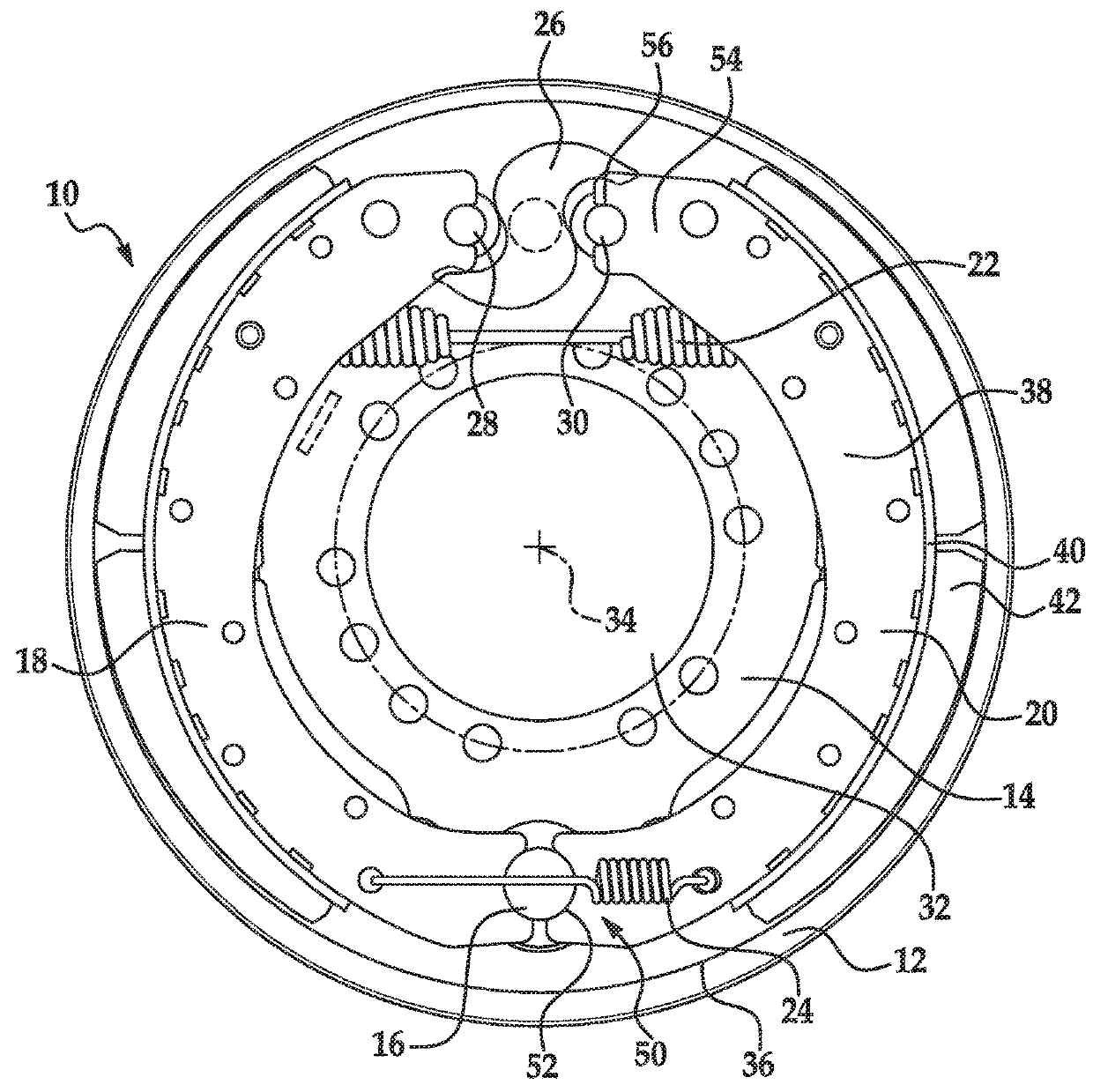
[0023]Referring now to the drawings wherein like reference numerals are used to identify identical components in the various views, FIG. 1 illustrates a drum brake 10. Brake 10 is provided to slow rotation of one or more vehicle wheels. Brake 10 is particularly adapted for use in heavy vehicles. It should be understood, however, that brake 10 may be used on a wide variety of vehicles and in non-vehicular applications. Brake 10 is configured to act against an annular brake drum 12 that rotates with the vehicle wheel or wheels at one end of an axle (not shown). Brake 10 may include a brake spider 14, one or more anchor pins 16, brake shoes 18, 20, return and retaining springs 22, 24, and means, such as cam 26 and rollers or cam followers 28, 30, for moving brake shoes 18, 20 between positions of engagement and disengagement with a braking surface.

[0024]Spider 14 is provided to mount the various components of brake 10. Spider 14 defines a central aperture 32 having a center axis 34 whi...


PUM


Abstract

A brake shoe for a drum brake includes a brake table and one or more webs supporting the brake table. One end of each web is pivotally coupled to an associated brake spider and another end of each web responds to a force applied by an actuator that causes the brake shoe to move between positions of engagement and disengagement with an associated braking surface. The brake shoe further includes means for damping movement of the brake shoe, during engagement of the brake shoe with the braking surface, for a natural frequency of the brake shoe having an order of at least two and a causing a bending modal shape of the brake shoe. In one embodiment, the damping means includes a damping plate disposed on one side of a web. A spring acts on a side of the plate opposite the web to urge the plate towards the web.

Description

CROSS-REFERENCE TO RELATED APPLICATIONS[0001]This application is a divisional application of U.S. patent application Ser. No. 14 / 948,735 filed Nov. 23, 2015, the entire disclosure of which is incorporated herein by reference.BACKGROUND OF THE INVENTIONa. Field of the Invention[0002]This invention relates to vehicle brakes. In particular, the invention relates to a brake shoe for a drum brake assembly that is configured to reduce resonance of the brake shoe during engagement of the brake to reduce brake noise.b. Background Art[0003]In a conventional drum brake, a drum rotates with a wheel or wheels proximate to one end of an axle. The drum defines a radially inner braking surface. A brake spider is disposed about the axle and a pair of brake shoes are pivotally mounted at one end to the brake spider. The opposite end of each brake shoe is engaged by an actuating member such as a cam to move the brake shoes between positions of engagement and disengagement with the braking surface of ...

Claims


Application Information

Patent Timeline
Patent Type & Authority Applications(United States)
IPC IPC(8): F16D65/00F16D65/08
CPCF16D65/0018F16D65/08
Inventor CHURCH, DAVID R.
Owner BENDIKS SPAJSER FAUNDEJSHN BREJK LLK
Why Eureka
Try Eureka