Stator fixed type eddy current retarder

A fixed and retarder technology, applied in the direction of asynchronous induction clutch/brake, etc., can solve the problems of low utilization rate of magnetic field, complicated winding of retarder, small braking torque, etc., to improve braking safety performance , to avoid the effect of brake thermal failure and large braking torque

Active Publication Date: 2013-08-21
江阴智产汇知识产权运营有限公司
View PDF4 Cites 8 Cited by
  • Summary
  • Abstract
  • Description
  • Claims
  • Application Information

AI Technical Summary

Problems solved by technology

The current retarder has complex winding, large volume, heavy mass, inconvenient installation, and low utilization rate of the magnetic field, so the braking torque is small
And the plane of the rotor is perpendicular to the axis. When the axial movement occurs, the rotor will scratch the stator and damage the retarder.

Method used


Image

  • Stator fixed type eddy current retarder
  • Stator fixed type eddy current retarder
  • Stator fixed type eddy current retarder

Examples


Embodiment Construction

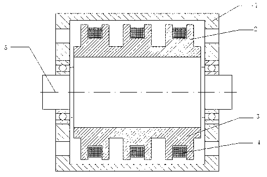
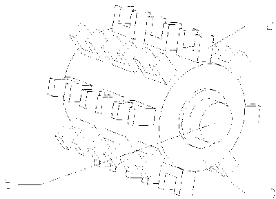
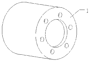
[0015] like figure 1 As shown, a fixed stator eddy current retarder according to the present invention includes an outer rotor 1 , a U-shaped stator yoke 2 , an inner stator 3 , an excitation coil 4 and a stator shaft 5 . see image 3 , The outer rotor 1 is a hollow cylindrical structure, and is fixed on the input end of the rear axle or the output end of the gearbox through a connecting flange. The inner stator 3 is coaxially sleeved inside the outer rotor 1, and the center of the inner stator 3 is coaxially fixedly connected to the stator shaft 5, and the two ends of the stator shaft 5 extend beyond the two ends of the outer rotor 1, and the two ends of the outer rotor 1 are supported by bearings on the stator shaft 5. The two ends of the stator shaft 5 are connected with the half shaft through couplings. The inner stator 3 can be designed as a hollow cylindrical structure, and the stator shaft 5 is fixedly sleeved in the central hole of the inner stator 3 .

[0016] see...


PUM


Abstract

The invention discloses a stator fixed type eddy current retarder which conducts braking and speed reducing on an automobile. The stator fixed type eddy current retarder comprises an outer rotor, an inner stator and a stator shaft, wherein the outer rotor is of a hollow-cylinder-shaped structure, a plurality of U-shaped stator magnet yokes are fixedly arranged on the outer ring surface of the inner stator, the bottom faces of all the U-shaped stator magnet yokes are fixedly arranged on the outer ring surface of the inner stator in the axial direction of the inner stator, a U-shaped opening of each U-shaped stator magnet yoke faces toward the inner surface of the outer rotor, and a gap is arranged between each U-shaped opening of each U-shaped stator magnet yoke and the inner surface of the outer rotor. The plurality of U-shaped stator magnet yokes are divided into m sets, the m sets of U-shaped stator magnet yokes are distributed at equal intervals in the axial direction of the inner stator, each set of U-shaped stator magnet yokes are composed of n U-shaped stator magnet yokes, the n U-shaped stator magnet yokes in each set are arranged in an equal-angle mode in the outer ring peripheral direction of the inner stator, and a magnet exciting coil is wound on each U-shaped opening of each U-shaped stator magnet yoke in each set. The magnetic field usage rate is high, under the condition that the same current is switched on, produced braking torque is large, and braking safety performance is good.

Description

technical field [0001] The invention relates to an eddy current retarder installed on an automobile to brake and decelerate the automobile. Using electromagnetic to generate braking torque, it is a kind of automobile auxiliary brake. Background technique [0002] With the development of the highway network, the speed of the car is getting faster and faster, and the braking load of the car is also increasing. Under the long-term continuous braking conditions, the traditional friction braking system is prone to brake heat fading, and the braking efficiency is greatly reduced or even completely disappeared. The use of non-contact eddy current auxiliary braking system can effectively solve the problem of thermal degradation of friction brakes and greatly improve the safety performance of automobiles. [0003] At present, most of the disc type eddy current retarders that have been widely used in passenger cars and trucks have the following structure: the stator part is composed...

Claims


Application Information

Patent Timeline
Patent Type & Authority Applications(China)
IPC IPC(8): H02K49/04
Inventor 顾晓丹何仁胡东海时俊张端军
Owner 江阴智产汇知识产权运营有限公司
Why Eureka
Try Eureka