
Wafer Chuck Apparatus With Contractible Sealing Devices For Securing Warped Wafers

a technology of contracting sealing and chuck, which is applied in the field of chucks, can solve the problems of too much leakage to generate the pressure differential needed

Inactive Publication Date: 2018-06-14
VEECO INSTR
View PDF3 Cites 9 Cited by
  • Summary
  • Abstract
  • Description
  • Claims
  • Application Information

AI Technical Summary

Benefits of technology

The invention relates to a wafer chuck apparatus that includes multiple sealing devices for improving its performance during semiconductor manufacturing processes. Specifically, this patent describes an embodiment with three or more sealing devices, which can provide better protection against contamination and improve vacuum levels within the chamber used for processing. Another technical effect is the use of at least two sealing devices on different sides of the wafer chuck, allowing for improved uniformity across the entire surface area of the substrate being processed.

Problems solved by technology

The technical problem addressed in this patent text relates to how to hold semiconductor wafers that have significant warping while performing lithography exposures needed for both chip fabrication and packaging. Vacuum chucks used for supporting wafers often cannot effectively handle these larger, more warped wafers without causing excessive leakage, making it difficult to achieve the required level of flattening.

Method used


Image

  • Wafer Chuck Apparatus With Contractible Sealing Devices For Securing Warped Wafers
  • Wafer Chuck Apparatus With Contractible Sealing Devices For Securing Warped Wafers
  • Wafer Chuck Apparatus With Contractible Sealing Devices For Securing Warped Wafers

Examples


generalized embodiment

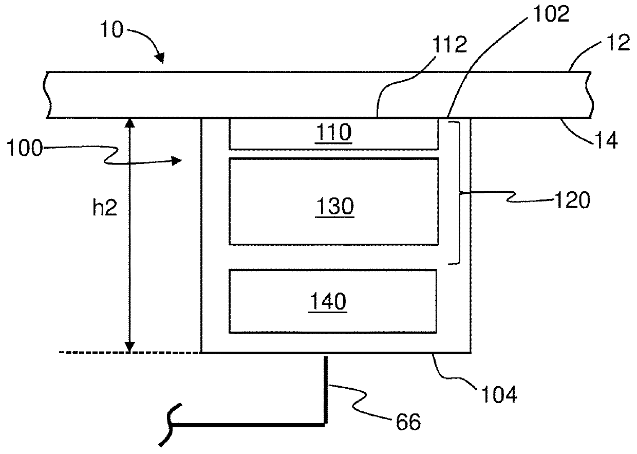
[0053]FIGS. 2A and 2B are schematic diagrams of a generalized embodiment of sealing device 100 in two different operating positions, namely an extended operating position (FIG. 2A) and a contracted operating position (FIG. 2B). Sealing device 100 has an upper end 102 and a lower end 104. Sealing device 100 has a height h1 in the extended operating position as measured between upper end 102 and lower end 104. Sealing device 100 also has a height h2 in the contracted operating position also measured from the upper end 102 to the lower end 104, where h1>h2. Sealing device 100 is pneumatically coupled to vacuum pump 70 (FIG. 1B) via vacuum line system 66 as discussed above.

[0054]Sealing device 100 includes at least one sealing member 110 that has a top end 112 that defines upper end 102 of the sealing device. Thus, top end 112 of sealing member 110 is capable of forming a vacuum seal with backside 14 of wafer 10 when the wafer and sealing device 100 are brought into contact, as shown in...

first example embodiment

[0057]FIGS. 4A through 4C are close-up x-z cross-sectional views of chuck 50 showing the details of a first example embodiment of sealing device 100 in the two different operating positions.

[0058]Sealing device 100 of FIGS. 4A through 4C show an example support member 130. Support member 130 has a top surface 132 and a bottom surface 134 and a perimeter 136. Support member 130 is sized to fit closely within recess 80 and in an example has the same general cylindrical shape as the recess. In an example, support member 130 is monolithic. In an example, there can be a small gap G between sidewall 84 of recess 80 and perimeter 136 of support member 130 (the size of gap G is exaggerated in the Figures for clarity). A vacuum channel 96 runs between top surface 132 and bottom surface 134. Top surface 132 supports sealing member 110. In an example, sealing member 110 can be in the form of a gasket, e.g., rubber gasket or O-ring.

[0059]Support member 130 is supported at bottom surface 134 by ...

second embodiment

[0064]FIGS. 5A through 5C are close-up x-z cross-sectional views of chuck 50 showing the details of a second example embodiment of sealing device 100 in two different operating positions. Sealing device 100 of FIGS. 5A through 5C is similar that shown in FIGS. 4A through 4C but includes a central pillar 90 within recess 80, as best seen in the top-down view of FIG. 6. Vacuum channel 96 runs in the z-direction through central pillar 90 and connects to vacuum line system 66 within chuck body 51. Central pillar 90 has a top surface 92 that in an example resides in the plane of upper surface 52 of chuck 50.

[0065]FIGS. 7A and 7B are top-down and top-elevated views, respectively, of an example support member 130 that has a donut shape with a central hole 138 sized to accommodate central pillar 90 so that support member 130 can be disposed within recess 80, with the central pillar extending into central hole 138. Resilient member 140 can also have a donut shape or can comprise a plurality ...


PUM


Abstract

A wafer chuck apparatus includes a chuck with a body and a vacuum line system formed within the body. The wafer chuck apparatus has sealing devices each operably disposed in respective recesses formed in the body at an upper surface of the chuck. Each sealing device is contractible between an expanded operating position and a contracted operating position. The top end of each sealing device is configured to form a vacuum seal with a corresponding portion of a backside of a wafer. The sealing devices extend above the upper surface of the chuck higher than typical seals and guide the wafer down to the upper surface of the chuck where it can be engaged by vacuum features that chuck the wafer to the upper surface of the chuck. The sealing devices are particularly useful for chucking warped wafers.

Description


Claims


Application Information

Patent Timeline
Owner VEECO INSTR
Learn More