Magnetic head for X-ray source

Inactive Publication Date: 2007-02-01
MOXTEK INC
View PDF42 Cites 52 Cited by
  • Summary
  • Abstract
  • Description
  • Claims
  • Application Information

AI Technical Summary

Benefits of technology

[0018] It has been recognized that it would be advantageous to develop a device for improved focusing and stability of an electron beam within an X-ray source, or a mobile, miniature X-ray source. It has also been recognize

Problems solved by technology

Typical high-power X-ray tubes are somewhat bulky and fragile.
Such X-ray tubes must be energized by large, high-voltage power supplies that limit the mobility of the devices.
This is inconvenient for many X-ray applications.
Unfortunately, the intensity of emission from 109Cd decays exponentially, with a half-life of about 1.2 years.
This necessitates frequent recalibration and eventual disposal of the isotope source.
The geometry of the referenced devices, however, is not ideal for miniature, portable XRF analysis.
Thus, medical X-ray tubes are inadequate for most in-situ XRF analysis because of the divergence of their X-ray output.
With respect to the '829 patent, an interesting nozzle is shown, but the rest of the apparatus is large and inadequate for mobile fieldwork.
The electromagnet is heavy and requires considerable power from a large battery, if it is to be mobile.
Additionally, the long anode of this configuration offers no benefit to typical analytical applications.
A drawback of the Wehnelt aperture is that it significantly limits electron flux exiting the cathode.
The field-shaping electrode, in effect, reduces the distance between anode and cathode, however; and it can increase the risk of electrical breakdown

Method used


Image

  • Magnetic head for X-ray source
  • Magnetic head for X-ray source

Examples


Embodiment Construction

[0025] Reference will now be made to the exemplary embodiments illustrated in the drawings, and specific language will be used herein to describe the same. It will nevertheless be understood that no limitation of the scope of the invention is thereby intended. Alterations and further modifications of the inventive features illustrated herein, and additional applications of the principles of the inventions as illustrated herein, which would occur to one skilled in the relevant art and having possession of this disclosure, are to be considered within the scope of the invention.

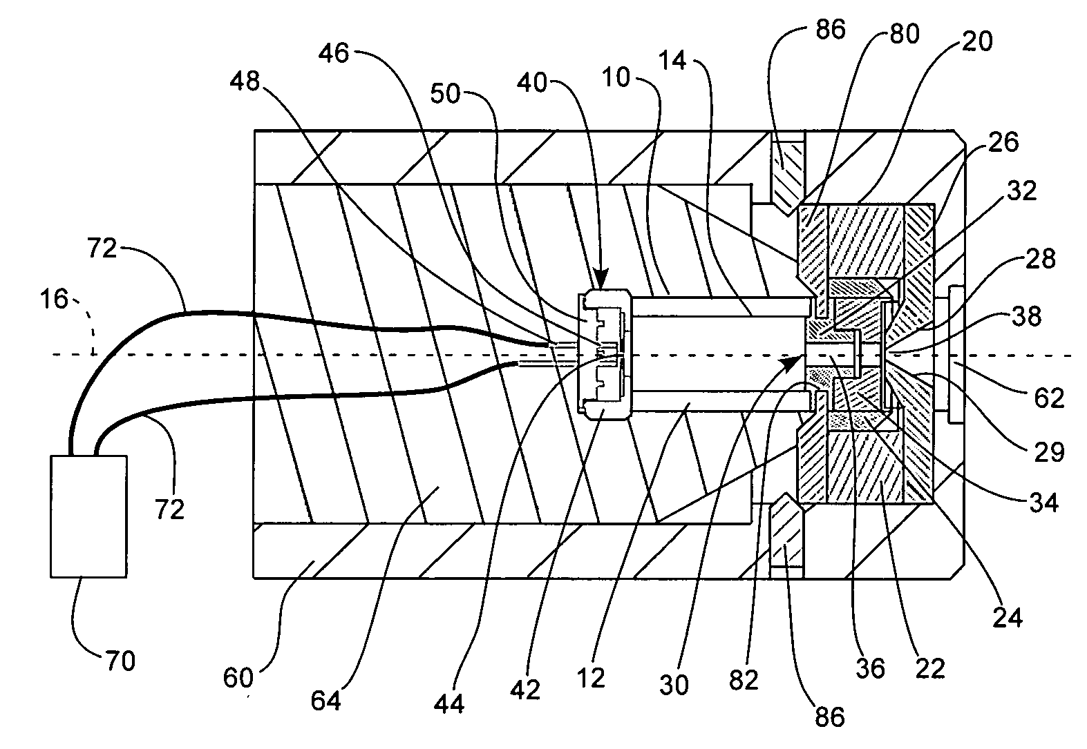
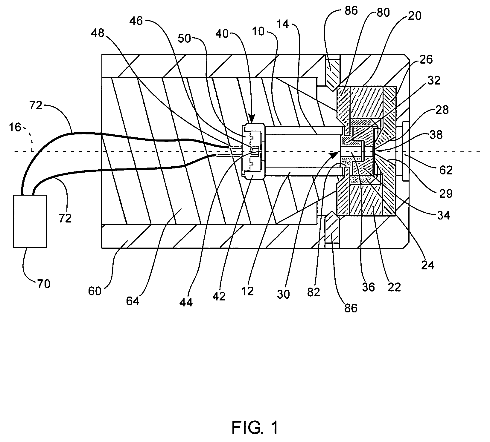
[0026] As illustrated in FIG. 1, a mobile, miniature X-ray source or tube, indicated generally at 10, in accordance with the present invention is shown. Various aspects of mobile, miniature X-ray sources are disclosed in U.S. Pat. No. 6,661,876, which is herein incorporated by reference. The X-ray source 10 advantageously includes a magnetic appliance, indicated generally at 20, coupled to the X-ray source 10 t...


PUM


Abstract

An X-ray source includes a magnetic appliance to provide electron beam focusing. The magnetic appliance can provide variably focused and non-focused configurations. The magnetic appliance can include one or more electromagnets and/or permanent magnets. An electric potential difference is applied to an anode and a cathode that are disposed on opposite sides of an evacuated tube. The cathode includes a cathode element to produce electrons that are accelerated towards the anode in response to the electric field between the anode and the cathode. The anode includes a target material to produce x-rays in response to impact of electrons.

Description

[0001] This application claims benefit to the priority of U.S. Provisional Application 60 / 667,250 filed Mar. 31, 2005 which is herein incorporated by reference in its entirety for all purposes.BACKGROUND OF THE INVENTION [0002] 1. Field of the Invention [0003] The present invention relates generally to an X-ray source with a focused electron beam. More particularly, the present invention relates to a miniature magnetic electron lens assembly for reducing the cross-section of an electron beam at its intersection with the anode target of a miniature, mobile X-ray tube, thereby reducing the size of its x-ray emitting region and increasing the local intensity of its X-ray output. [0004] 2. Related Art [0005] In an X-ray tube, electrons emitted from a cathode are accelerated toward an anode by an electric field produced by a bias voltage maintained between the two electrodes. The intervening space must be evacuated to avoid electron energy loss and scattering through collisions with gas ...

Claims


Application Information

Patent Timeline
IPC IPC(8): H01J35/14
CPCH01J35/14H01J35/16H05G1/04H01J2235/165H01J2235/087H01J35/116H01J35/153H01J35/147
Inventor BARD, ERIKJENSEN, CHARLESREYES, ARTUROOGDEN, SHAUNLIDDIARD, STEVEN
Owner MOXTEK INC
Why Eureka
Try Eureka