
Fluid collection device having tilting retractable needle

a technology of a collection device and a retractable needle, which is applied in the field of fluid collection devices, can solve the problems of increasing the cost of manufacturing the device, uninfected medical personnel, and the transmission of various pathogens

Inactive Publication Date: 2009-04-07
MDC INVESTMENT HLDG
View PDF38 Cites 55 Cited by
  • Summary
  • Abstract
  • Description
  • Claims
  • Application Information

AI Technical Summary

Benefits of technology

[0010]Yet another object of the invention is to provide a pocket for receiving and protecting the rearward sharpened tip of the needle when the needle is disposed in the retracted position. The pocket may be formed in a cylindrical insert that lines the housing. Preferably, the insert further includes a wing projecting forwardly and intersecting the guide. The wing has a lower edge configured in the shape of the transverse portion of the track, wherein the lower edge of the wing forms a sidewall of the transverse portion of the track.

Problems solved by technology

Handling of such needle-bearing medical devices after the needle is withdrawn from the patient can result in transmission of various pathogens, most notably human immune virus (HIV), to uninfected medical personnel, due to an inadvertent needle stick.
The known devices suffer from one of several problems, including complicated structures that increase the cost of manufacturing the device.
A safety needle product may be safe, but if it is too expensive, it will not be accepted, and the benefits of the safety product will never be recognized by the medical community.
In addition, many devices require awkward or cumbersome actions to cause the needle to retract.
The more complicated it is to retract a needle, the less likely it is that the medical professional will take the time to retract the needle, particularly in emergency situations.
In addition, in the field of phlebotomy, many of the known devices do not adequately protect against inadvertent contact with the non-patient tip of the needle.
The known medical devices do not adequately address the protection needed to efficiently shield both the forward and rearward ends of the needle.

Method used


Image

  • Fluid collection device having tilting retractable needle
  • Fluid collection device having tilting retractable needle
  • Fluid collection device having tilting retractable needle

Examples


Embodiment Construction

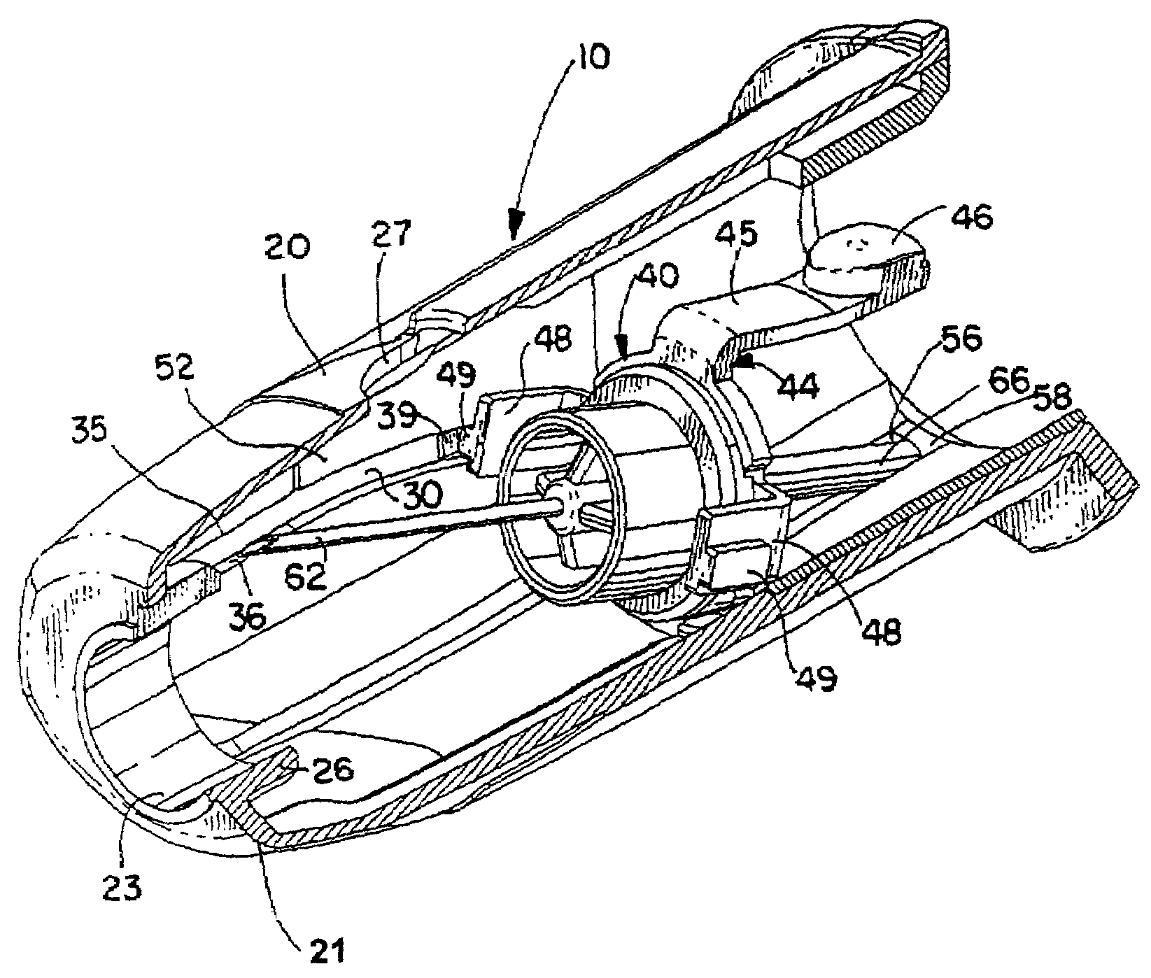
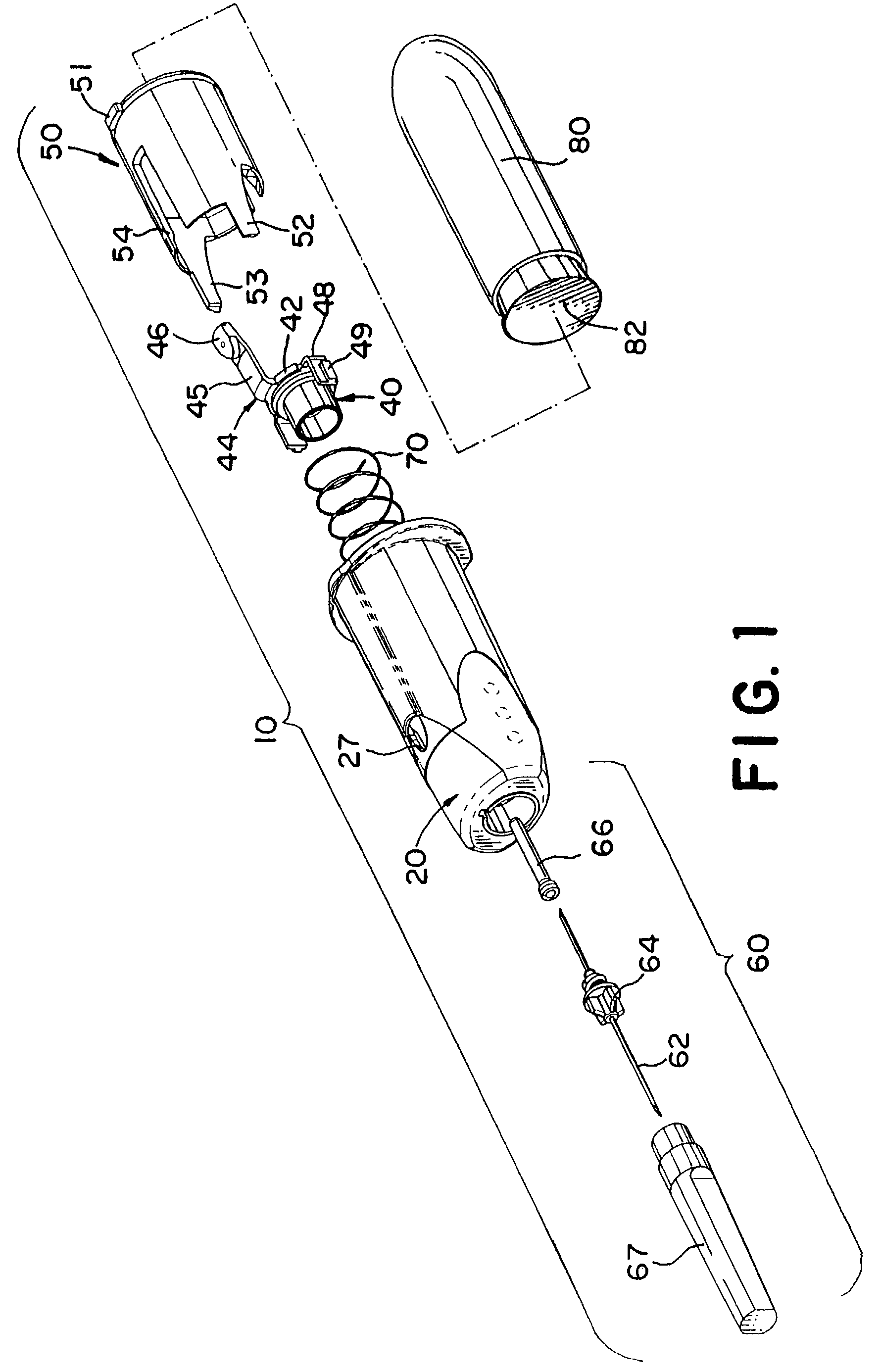
[0021]Referring to the drawings in general, and to FIG. 1 specifically, a needle-bearing medical device is designated generally 10. The device 10 is operable in connection with a fluid container 80, such as a fluid sampling container for use in drawing blood samples. The device 10 includes a double ended needle 62. The forward end of the needle is inserted into the patient and the rearward end of the needle pierces a seal 82 on the container 80. After use, the container is removed, and if desired, further containers 80 are used to take further samples while the forward end of the needle remains in the patient. After the last container 80 is removed, the needle is retracted into the device 10 to protect against inadvertent contact with the contaminated needle.

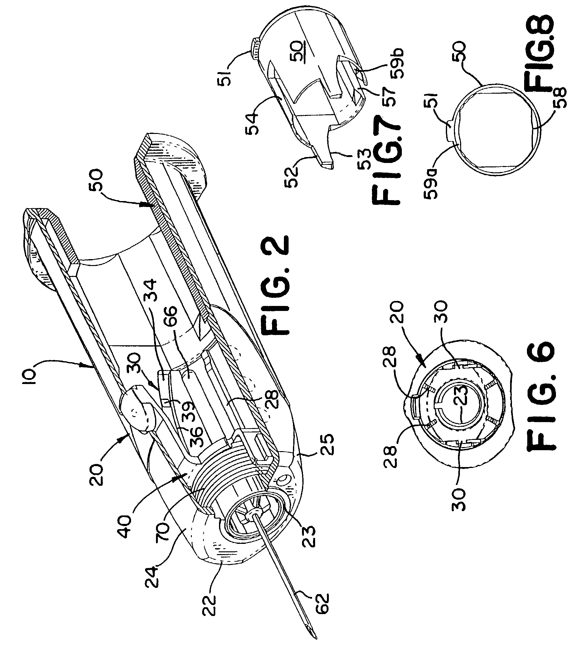
[0022]As shown in FIG. 1, the device includes five elements or subassemblies: a needle assembly 60, a substantially hollow barrel 20, a spring 70, a needle holder 40, and an insert 50. Referring to FIG. 4, the needle 62 projects...


PUM


Abstract

A medical device is provided for collecting fluid samples from a patient, such as blood samples. The device includes a needle having a forward sharpened tip that is retracted into the housing of the device after use to prevent exposure to the contaminated needle. The rearward end of the housing is open, forming a socket for receiving a fluid container, such as a vacuum tube, that will receive the fluid sample. A needle retainer releasably retains the needle in the extended position against the rearward bias of a biasing element. After use, the medical professional retracts the needle by pressing an actuation button, allowing the biasing element to displace the needle rearwardly. A guide track guides the needle during retraction, tilting the needle off-axis.

Description

CROSS REFERENCE TO RELATED APPLICATION[0001]This application is a continuation of U.S. application Ser. No. 09 / 588,151 filed Jun. 5, 2000, now U.S. Pat. No. 6,524,276, issued Feb. 25 2003, which is hereby incorporated herein by reference.FIELD OF THE INVENTION[0002]The present invention relates to fluid collection devices for sampling fluid from a patient. More specifically, the invention relates to such a device having a retractable needle feature for rendering the device non-reusable and safely disposable.BACKGROUND OF THE INVENTION[0003]Various types of medical devices employ a needle for piercing the skin of a patient for diagnostic or therapeutic purposes. One such device is a phlebotomy or blood collection device that includes a needle for piercing a blood vessel of the patient to allow blood to be sampled from the patient. When the needle is inserted into the blood vessel of the patient, blood is withdrawn through the needle into a vacuum collection tube. Handling of such nee...

Claims


Application Information

Patent Timeline
Patent Type & Authority Patents(United States)
IPC IPC(8): A61M5/00A61M5/32A61B5/15
CPCA61B5/1444A61M5/3232A61B5/15003A61B5/150389A61B5/150496A61B5/150732A61B5/154A61B5/150656A61M2005/3206A61B5/150572A61B5/150717A61B5/150587
Inventor HALSETH, THOR R.BOTICH, MICHAEL J.MCWETHY, ROBERT T.
Owner MDC INVESTMENT HLDG
Learn More