Low-photon flux image-intensified electronic camera

a technology of low-pass filter and electronic camera, which is applied in the field of low-pass filter image-intensified electronic camera, can solve the problems of long imaging time, low light level of such tissues can be electronically obscured, and two cannot be simultaneously shuttered, so as to achieve low noise, reduce background, and achieve high gain

Active Publication Date: 2006-04-20
STANFORD PHOTONICS
View PDF1 Cites 55 Cited by
  • Summary
  • Abstract
  • Description
  • Claims
  • Application Information

AI Technical Summary

Benefits of technology

[0018] An advantage of the present invention is that a low-photon flux image-intensified electronic camera is provided with significantly reduced background, zero effective read noise, and high gain that can be used to image single photons.
[0019] Another advantage of the present invention is that a low-photon flux image-intensified electronic camera is provided that can produce real-time images of single photon events with zero or near zero sensor background noise.
[0020] A further advantage of the present invention is that a low-photon flux image-intensified electronic camera is provided in which real-time and integrated modes can both be used.
[0021] A still further advantage of the present invention is that a low-photon flux image-intensified electronic camera is provided in which off-chip digital integration can be used because the dark currents and hot pixels are substantially reduced.
[0022] Embodiments of the present invention permit freedo

Problems solved by technology

But the two cannot be simultaneously shuttered because of the vast difference in light levels.
Very low light levels from such tissues can be electronically obscured by the background noise or dark currents thermally generated by camera image devices.
Prior-art intensified cameras needed long imaging times and suffer from spurious noise events, high dark counts, high integrated background levels that build with long exposures, and high amplitude “scintillation” ion-feedback noise.
Conventional bi-alkali material photocathodes used in intensified platforms have low quantum efficiencies, high background noise, poor resolution and cosmetic quality, and are typically lens-coupled to a charge-coupled device (CCD).
Lens-coupling is relatively inefficient and reduces light-collection efficiencies.
Hig

Method used


Image

  • Low-photon flux image-intensified electronic camera
  • Low-photon flux image-intensified electronic camera

Examples


Embodiment Construction

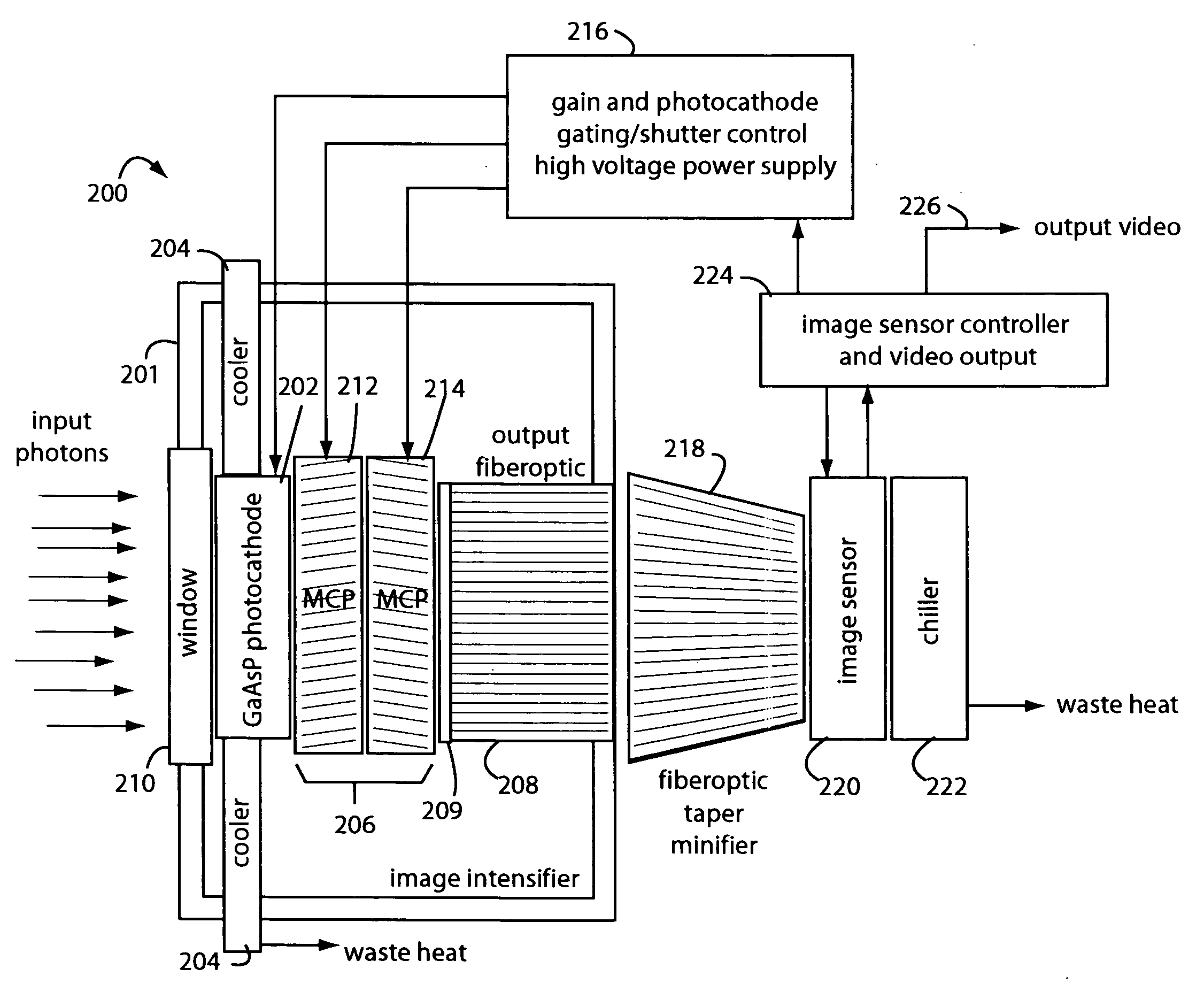
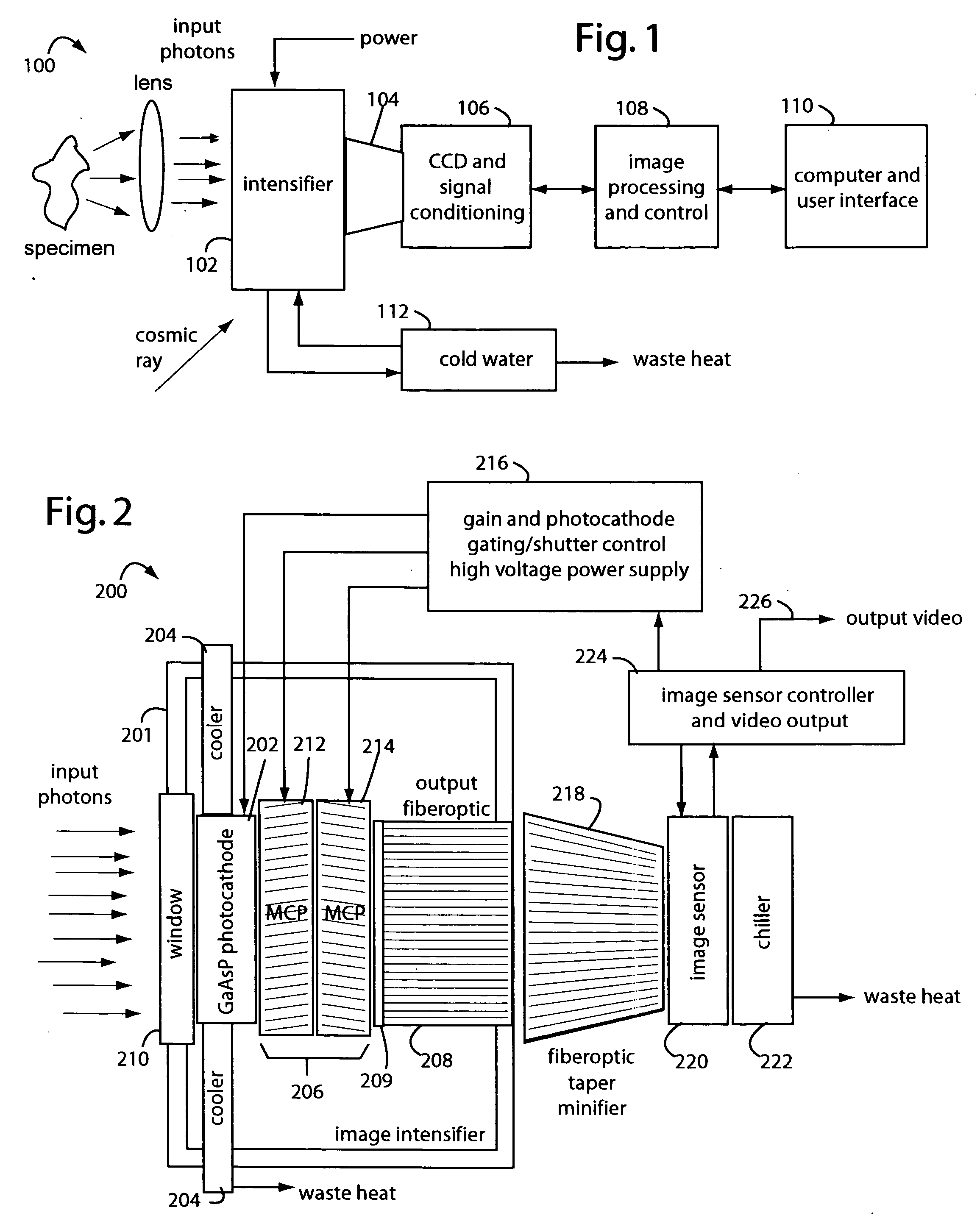
[0027]FIG. 1 represents an intensified camera system embodiment of the present invention, and is referred to herein by the general reference numeral 100. The intensified camera system 100 collects bioluminescent light photons through a lens from a specimen on an image intensifier 102. Such can be used for separately imaging and then combining reference photos of the specimens and their exceedingly faint bioluminescent emissions. A tapered fiberoptic coupling 104 collects an intensified image produced on the backside of the image intensifier 102 and relays it to a CCD camera 106. An electronic rendering of the photon image is received by an image processor 108 that can make long exposures by digitally integrating frames. Results are sent to a computer and user display 110.

[0028] The CCD camera 106 must be a very high quality or scientific-grade device so the image intensifier 102 can be set at lower gain values. Cooling the CCD camera 106 will improve results too by elimination of s...


PUM


Abstract

A low-photon flux image-intensified electronic camera comprises a gallium arsenide phosphide (GaAsP) photocathode in a high vacuum tube assembly behind a hermetic front seal to receive image photons. Such is cooled by a Peltier device to −20° C. to 0° C., and followed by a dual microchannel plate. The microchannels in each plate are oppositely longitudinally tilted away from the concentric to restrict positive ions that would otherwise contribute to the generation high brightness “scintillation” noise events at the output of the image. A phosphor-coated output fiberoptic conducts intensified light to an image sensor device. This too is chilled and produces a camera signal output. A high voltage power supply connected to the dual microchannel plate provides for gain control and photocathode gating and shuttering. A fiberoptic taper is used at the output of the image intensifier vacuum tube as a minifier between the internal output fiberoptic and the image sensor.

Description

BACKGROUND OF THE INVENTION [0001] 1. Field of the Invention [0002] The present invention relates to low-photon flux image-intensified electronic cameras, and in particular to ones that use gallium arsenide phosphide photocathodes and intensifier tubes chilled below zero degrees centigrade with a dual microchannel plate structure, and without an ion barrier film. [0003] 2. Description of the Prior Art [0004] Bioluminescent living tissues can be engineered for use in medical studies of live animals, plant cells, plants, and vitro biological samples. A good background in this area was published in the Journal of Biomedical Optics 6(4), 432-440 (October 2001), by B. W. Rice, et al., in an article titled, “In vivo imaging of light-emitting probes.”[0005] If the bioluminescent tissues are on the surface of an organism, the light emitted can be relatively easy to image with a camera. But if the bioluminescent tissues are internal organs or other structures like tumors, the intervening tis...

Claims


Application Information

Patent Timeline
IPC IPC(8): H01L25/00
CPCH01J31/507H01J2201/3423H01J2231/50073H01J2231/5016
Inventor BUCHIN, MICHAEL P.
Owner STANFORD PHOTONICS
Why Eureka
Try Eureka