Systems and methods for determining track location and/or direction of travel

a technology of track location and direction, applied in the direction of railway signalling, railway signalling, signalling indicators on vehicles, etc., can solve the problems of reducing the safety aspect gps position information is typically not accurate enough to distinguish, and the requirement for crew interaction of the ptc system is reduced. , the effect of reducing uncertainty

Active Publication Date: 2018-06-21
WESTINGHOUSE AIR BRAKE TECH CORP
View PDF1 Cites 11 Cited by
  • Summary
  • Abstract
  • Description
  • Claims
  • Application Information

AI Technical Summary

Benefits of technology

[0005]Generally, provided are an improved system and computer-implemented method for determining a track location and a direction of travel of a train, preferably for use in connection with trains located in a track network. Preferably, provided are a system and computer-implemented method that reduce a crew interaction requirement of PTC systems. Preferably, provided are a system and computer-implemented method that can reduce uncertainty associated with a track location and / or a direction of travel of a train determined based on GPS position reports. Preferably, provided are a system and computer-implemented method for determining a track location and a direction of travel of a train that enable the track location and the direction of travel of the train to be determined with greater accuracy, provide improved safety for train and other vehicles in the transit network, and enable PTC systems to protect the train at an earlier time.

Problems solved by technology

However, GPS position reports tend to drift around within an accuracy bubble over time and space.
The location or position information from a single locomotive is typically not accurate enough to distinguish which track the locomotive is on when in an area with multiple parallel or crossing tracks, for example, in a train yard including ladder tracks.
Crew interaction and input, however, lowers a safety aspect of the PTC system because it allows for human error to be introduced.

Method used


Image

  • Systems and methods for determining track location and/or direction of travel
  • Systems and methods for determining track location and/or direction of travel
  • Systems and methods for determining track location and/or direction of travel

Examples


Embodiment Construction

[0062]For purposes of the description hereinafter, the terms “upper”, “lower”, “right”, “left”, “vertical”, “horizontal”, “top”, “bottom”, “lateral”, “longitudinal” and derivatives thereof shall relate to the invention as it is oriented in the drawing figures. It is to be understood that the invention may assume various alternative variations and step sequences, except where expressly specified to the contrary. It is also to be understood that the specific devices and processes illustrated in the attached drawings, and described in the following specification, are simply exemplary embodiments of the invention. Hence, specific dimensions and other physical characteristics related to the embodiments disclosed herein are not to be considered as limiting.

[0063]As used herein, the terms “communication” and “communicate” refer to the receipt, transmission, or transfer of one or more signals, messages, commands, or other type of data. For one unit or device to be in communication with anot...


PUM


Abstract

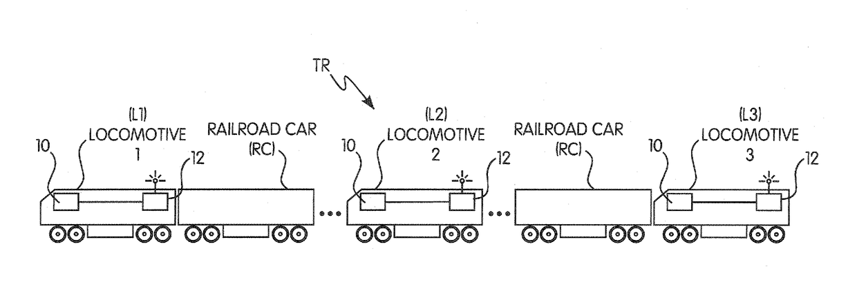
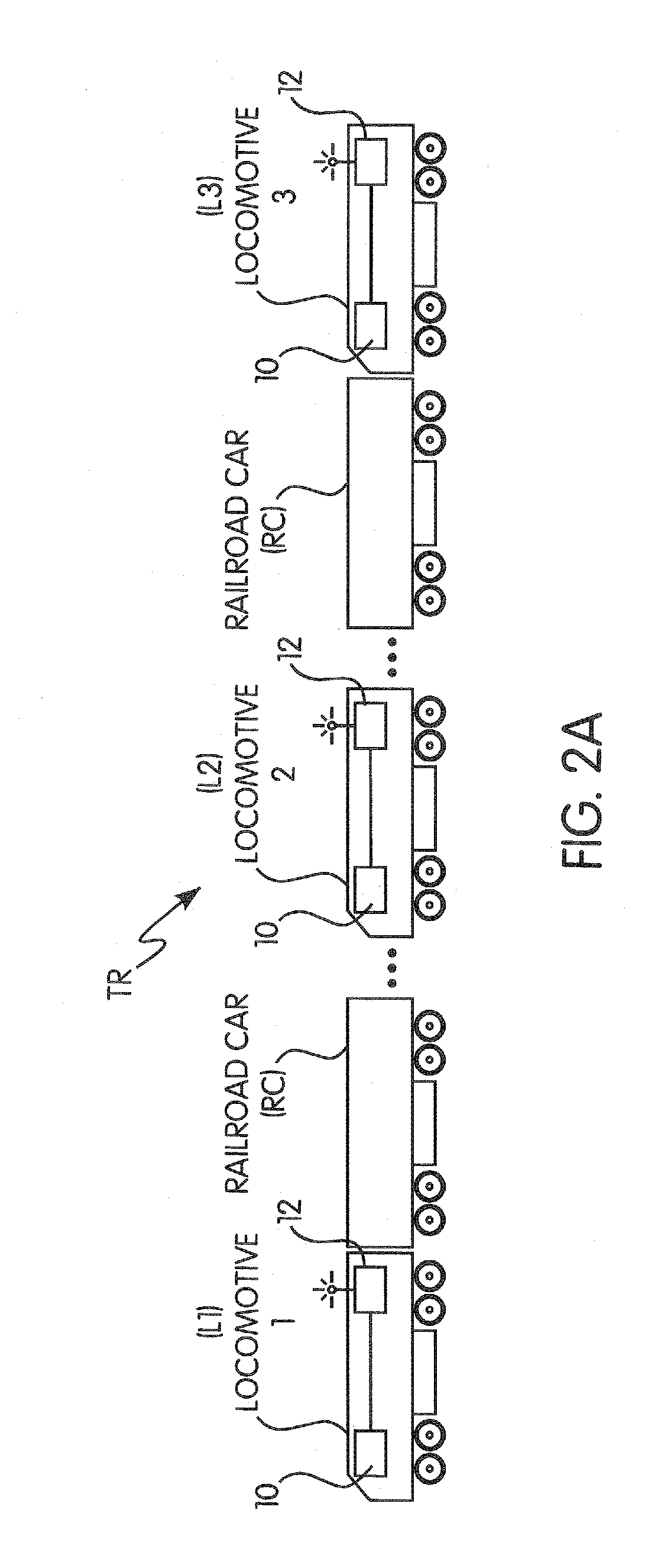
A system and method for determining a track location and/or a direction of travel of a train includes at least one computer programmed or configured to determine at least one of a track on which the train is located and a direction of travel of the train on the track based at least partly on at least one location associated with at least one locomotive or control car of the train and at least one other location associated with at least one other locomotive or control car of the train. The at least one computer can be programmed or configured to determine a track on which the train is located based at least partly on the at least one location associated with the at least one locomotive or control car of the train and at least one additional location associated with at least one additional locomotive or control car of at least one additional train.

Description

BACKGROUND OF THE INVENTIONField of the Invention[0001]This invention relates generally to a system and method for determining the position or location and / or direction of travel of vehicles in a transit network and, in particular, to a system and method for determining a track location and / or a direction of travel of a train or locomotive in a track network made up of multiple interconnected tracks.Description of Related Art[0002]Vehicle systems and networks exist throughout the world, and, at any point in time, a multitude of vehicles, such as cars, trucks, buses, trains, and the like, are travelling throughout the system and network. With specific reference to trains travelling in a track network, the locomotives of such trains are typically equipped with or operated using train control, communication, and management systems (e.g., positive train control (PTC) systems), such as the I-ETMS® of Wabtec Corp. In order to effectively manage all of the trains, navigation and enforcemen...

Claims


Application Information

Patent Timeline
Patent Type & Authority Applications(United States)
IPC IPC(8): B61L25/02
CPCB61L25/025B61L25/028B61L15/0018B61L2205/04B61L25/023B61L15/0027B61L25/021
Inventor OSWALD, JAMES A.KERNWEIN, JEFFREY D.
Owner WESTINGHOUSE AIR BRAKE TECH CORP
Why Eureka
Try Eureka