Capacitive sensing circuits and methods for determining eyelid position using the same

a sensing circuit and capacitive technology, applied in the field of electromechanical ophthalmic devices, can solve the problems that clinical methods may not be suitable for non-clinical settings, and achieve the effect of restoring communication and functionality and complex functions

Inactive Publication Date: 2018-06-21
JOHNSON & JOHNSON VISION CARE INC
View PDF4 Cites 7 Cited by
  • Summary
  • Abstract
  • Description
  • Claims
  • Application Information

AI Technical Summary

Benefits of technology

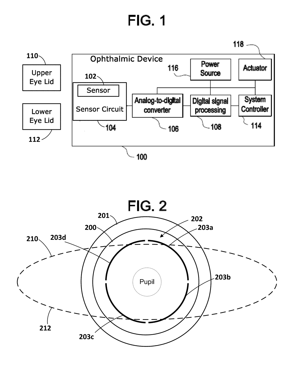
[0007]The present disclosure relates to powered ophthalmic devices that comprise an electronic system and performs a number of functions, including actuating a variable-focus optic if included. The electronic system includes one or more batteries or other power sources, power management circuitry, one or more sensors, sensor configurations, control algorithms, circuitry comprising a capacitive sensor, and lens driver circuitry.
[0008]In accordance with another aspect, the present disclosure is directed to powered ophthalmic lenses. Such lenses comprise a contact lens and an eye gaze tracking system incorporated into the contact lens, the eye gaze tracking system including a sensor to determine and track eye position, a system controller cooperatively associated with the sensor, the system controller configured to determine and track gaze direction in spatial coordinates based on information from the sensor output a control signal, and at least one actuator configured to receive the output control signal and implement a predetermined function.
[0009]In accordance with yet another aspect, the present disclosure is directed to an eyelid position sensing system for a powered ophthalmic device. The eyelid position sensing system may comprise a first electrode configured to be selectively overlaid by one or more of an upper eyelid and a lower eyelid of a user. The eyelid position sensing system may comprise a second electrode configured to be selectively overlaid by one or more of an upper eyelid and a lower eyelid of a user. The eyelid position sensing system may comprise a system controller cooperatively associated with the first electrode and the second electrode to receive a capacitance measurement therefrom, the system controller configured to determine a position of one or more of the upper eyelid and the lower eyelid in spatial coordinates based on the capacitance measurement received from the first electrode and the second electrode.
[0010]In accordance with yet another aspect, the present disclosure is directed to a powered ophthalmic device. The powered ophthalmic device may comprise a lens including an optic zone and a peripheral zone. The powered ophthalmic device may comprise an eye gaze tracking system incorporated into the peripheral zone of the contact lens, the eye gaze tracking system including a capacitive touch sensor to detect a capacitance based at least on a position of one or more of an upper eyelid and a lower eyelid, a system controller cooperatively associated with the capacitive touch sensor, the system controller configured to determine gaze direction in spatial coordinates based on information received from the sensor, and at least one actuator configured to receive the output control signal and implement a predetermined function.
[0011]Eye tracking is the process of determining either or both where an individual is looking, point of gaze, or the motion of an eye relative to the head. An individual's gaze direction is determined by the orientation of the head and the orientation of the eyes and / or configuration of eyelid position. More specifically, the orientation of an individual's head determines the overall direction of the gaze while the orientation of the individual's eyes determines the exact gaze direction which in turn is limited by the orientation of the head. Information of where an individual is gazing provides the ability to determine the individual's focus of attention and this information may be utilized in any number of disciplines or application, including cognitive science, psychology, human-computer interaction, marketing research and medical research. For example, eye gaze direction may be utilized as a direct input into a controller or computer to control another action. In other words, simple eye movements may be utilized to control the actions of other devices, including highly complex functions. Simple eye movements may be utilized in a manner similar to “swipes” which have become common in touch-screen and smartphone applications, for example, swiping to unlock a device, change applications, change pages, zoom in or out and the like. Eye gaze tracking systems are presently utilized to restore communication and functionality to those who are paralyzed, for example, using eye movements to operate computers. Eye tracking or gaze tracking may also be utilized in any number of commercial applications, for example, what individuals are paying attention to when they are watching television, browsing websites and the like. The data collected from this tracking may be statistically analyzed to provide evidence of specific visual patterns. Accordingly, information garnered from detecting eye or pupil movement may be utilized in a wide range applications. There are a number of currently available devices for tracking eye movement, including video-based eye trackers, search coils and arrangements for generating electrooculograms. Search coils or inductive sensors are devices which measure the variations of the surrounding magnetic fields. Essentially, a number of coils may be imbedded into a contact lens type device and the polarity and amplitude of the current generated in the coils varies with the direction and angular displacement of the eye. An electrooculogram is generated by a device for the detection of eye movement and eye position based on the difference in electrical potential between electrodes placed on either side of the eye. All of these devices are not suitable for use with a wearable, comfortable electronic ophthalmic lens or powered contact lens. Therefore, in accordance with another exemplary embodiment, the present disclosure is directed to a powered contact lens comprising a gaze sensor incorporated directly into the contact lens.

Problems solved by technology

However, such clinical methods may not be suitable for non-clinical settings, such as a everyday wear.

Method used


Image

  • Capacitive sensing circuits and methods for determining eyelid position using the same
  • Capacitive sensing circuits and methods for determining eyelid position using the same
  • Capacitive sensing circuits and methods for determining eyelid position using the same

Examples


Embodiment Construction

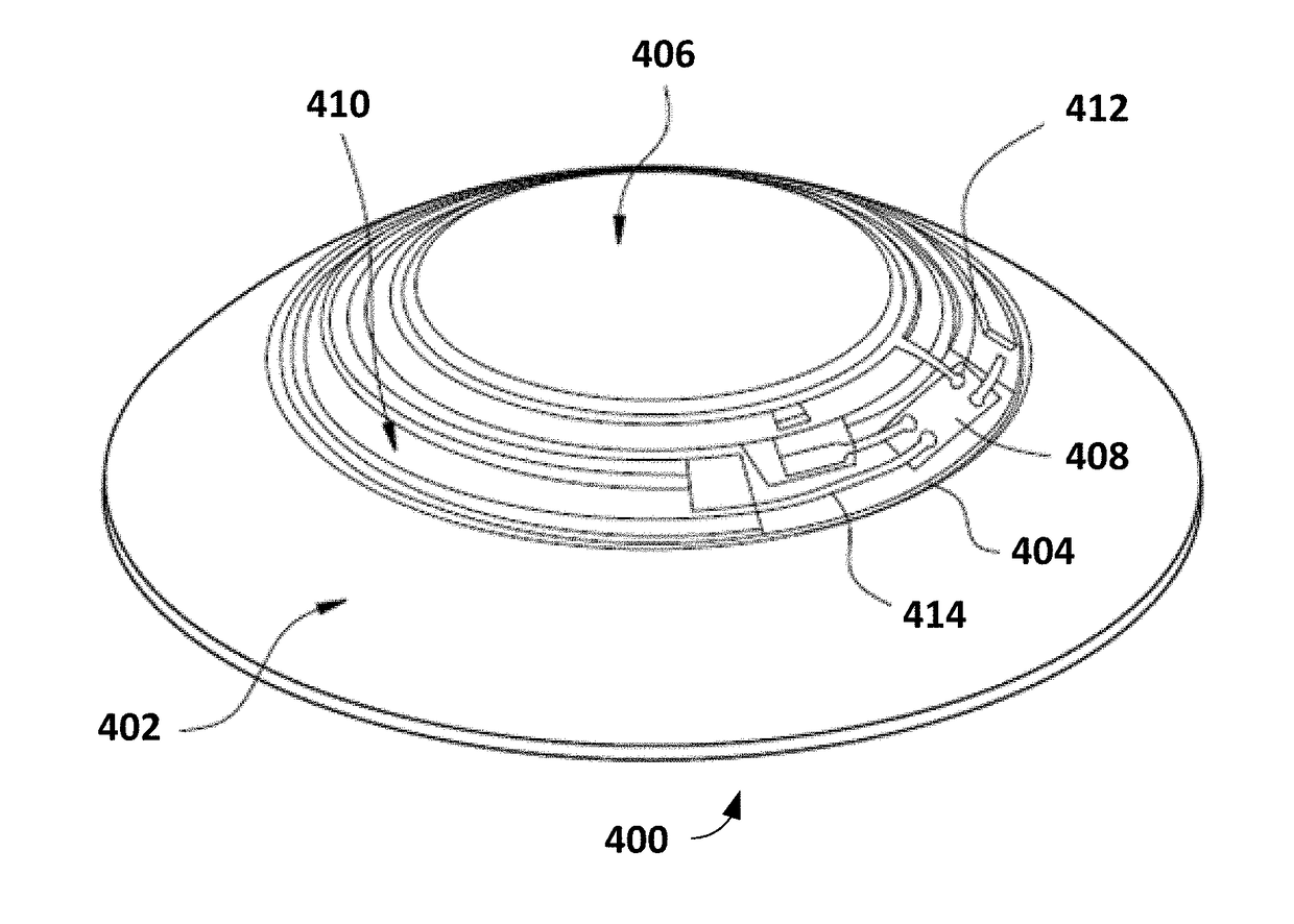
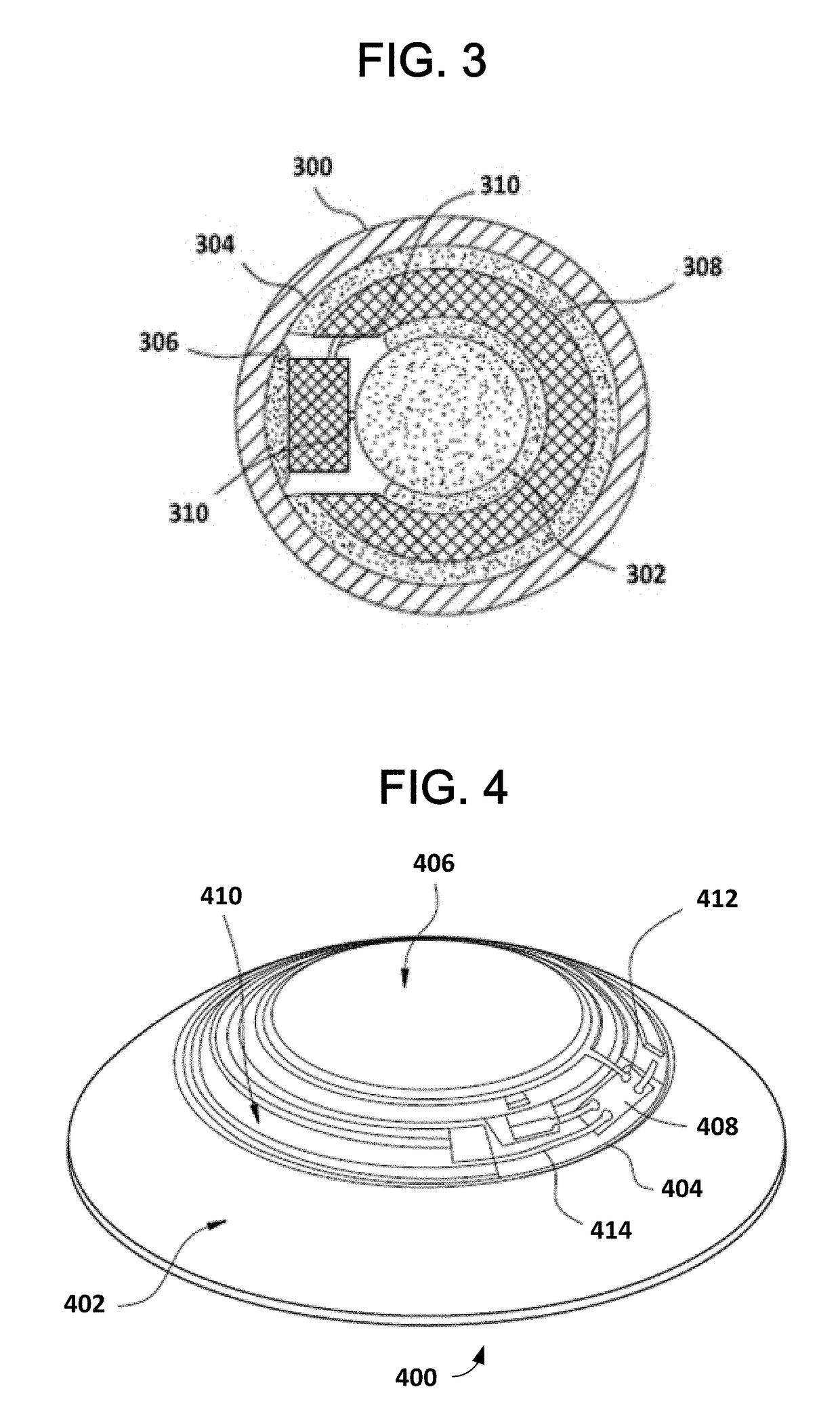
[0041]Ophthalmic devices may include contact lenses. Conventional contact lenses are polymeric structures with specific shapes to correct various vision problems as briefly set forth above. To achieve enhanced functionality, various circuits and components may be integrated into these polymeric structures. For example, control circuits, microprocessors, communication devices, power supplies, sensors, actuators, light-emitting diodes, and miniature antennas may be integrated into contact lenses via custom-built optoelectronic components to not only correct vision, but to enhance vision as well as provide additional functionality as is explained herein. Electronic and / or powered contact lenses may be designed to provide enhanced vision via zoom-in and zoom-out capabilities, or simply to modify the refractive capabilities of the lenses. Electronic and / or powered contact lenses may be designed to enhance color and resolution, to display textural information, to translate speech into cap...


PUM


Abstract

The present disclosure relates to sensor systems for electronic ophthalmic devices. In certain embodiments, the sensor systems may comprise a first electrode configured to be selectively overlaid by one or more of an upper eyelid and a lower eyelid of a user, a second electrode configured to be selectively overlaid by one or more of an upper eyelid and a lower eyelid of a user, and a system controller cooperatively associated with the first electrode and the second electrode to receive a capacitance measurement therefrom, the system controller configured to determine a position of one or more of the upper eyelid and the lower eyelid in spatial coordinates based on the capacitance measurement received from the first electrode and the second electrode.

Description

BACKGROUND OF THE DISCLOSURE1. Field of the Disclosure[0001]The present disclosure relates to electronic ophthalmic devices, such as wearable lenses, including contact lenses, implantable lenses, including intraocular lenses (IOLs) and any other type of device comprising optical components, and more particularly, to sensors and associated hardware and software for determining eyelid position in an individual to activate and control electronic ophthalmic devices.2. Discussion of the Related Art[0002]Lenses, such as contact lenses and intraocular lenses, currently are utilized to correct vision defects such as myopia (nearsightedness), hyperopia (farsightedness), presbyopia and astigmatism. However, properly designed lenses incorporating additional components may be utilized to enhance vision as well as to correct vision defects.[0003]Conventional contact lenses are polymeric structures with specific shapes to correct various vision problems as briefly set forth above. To achieve enha...

Claims


Application Information

Patent Timeline
Patent Type & Authority Applications(United States)
IPC IPC(8): G02C7/08A61B3/113G02C7/04A61F2/16
CPCG02C7/083A61F2/1629G02C7/04A61B3/113A61B3/0025G06F3/013A61H5/00A61H2205/024A61B3/14
Inventor BARROWS, COREY KENNETHBUSH, JOHN MICHAELHOGGARTH, STEVEN PHILIPTONER, ADAM
Owner JOHNSON & JOHNSON VISION CARE INC
Why Eureka
Try Eureka