
Unmanned aircraft navigation system and method

a technology for navigation systems and unmanned aircraft, applied in the field of unmanned aircraft, can solve the problems of low success rate, difficult piloting of these systems, and the fact that unmanned aircraft crashes must become extremely rar

Active Publication Date: 2018-06-21
AEROVIRONMENT INC
View PDF9 Cites 24 Cited by
  • Summary
  • Abstract
  • Description
  • Claims
  • Application Information

AI Technical Summary

Benefits of technology

The patent text describes a solution for landing an unmanned aircraft on a moving vehicle. The invention uses sensors on both the aircraft and the mobile structure to identify a specific area for landing and estimate the future position of the surface of that area. The aircraft then executes a landing maneuver to touch down on the surface of the mobile structure at the desired position. This technology is important for enabling a wide range of applications, such as maritime security and surveillance, fish spotting, and traffic enforcement.

Problems solved by technology

Today, multiple commercial uses for unmanned aircraft are being explored, with low levels of success because civilian unmanned aircraft are typically operated in a wide variety of conditions, by people with varying levels of skill.
A significant problem for commercial and hobbyist deployment of unmanned aircraft is the difficulty involved in piloting these systems, particularly when unmanned aircraft are being operated in harsh physical environments.
Unmanned aircraft crashes must become extremely rare as the cost and complexity of the sensor systems attached to unmanned aircraft continues to increase.
However, the unmanned aircraft industry still lacks the necessary autonomy for an unmanned aircraft to take off and land repeatedly and successfully without crashing.
These crashes are often attributable to human error.
However, these efforts have only been partially successful and completely fail to address the challenges inherent in landing an unmanned aircraft on a structure that is not stationary.
And because the level of difficulty involved in making this type of landing is known to be exceptionally high for a human pilot, autonomous takeoff and landing of an unmanned aircraft on a mobile structure is extremely challenging.

Method used


Image

  • Unmanned aircraft navigation system and method
  • Unmanned aircraft navigation system and method
  • Unmanned aircraft navigation system and method

Examples


Embodiment Construction

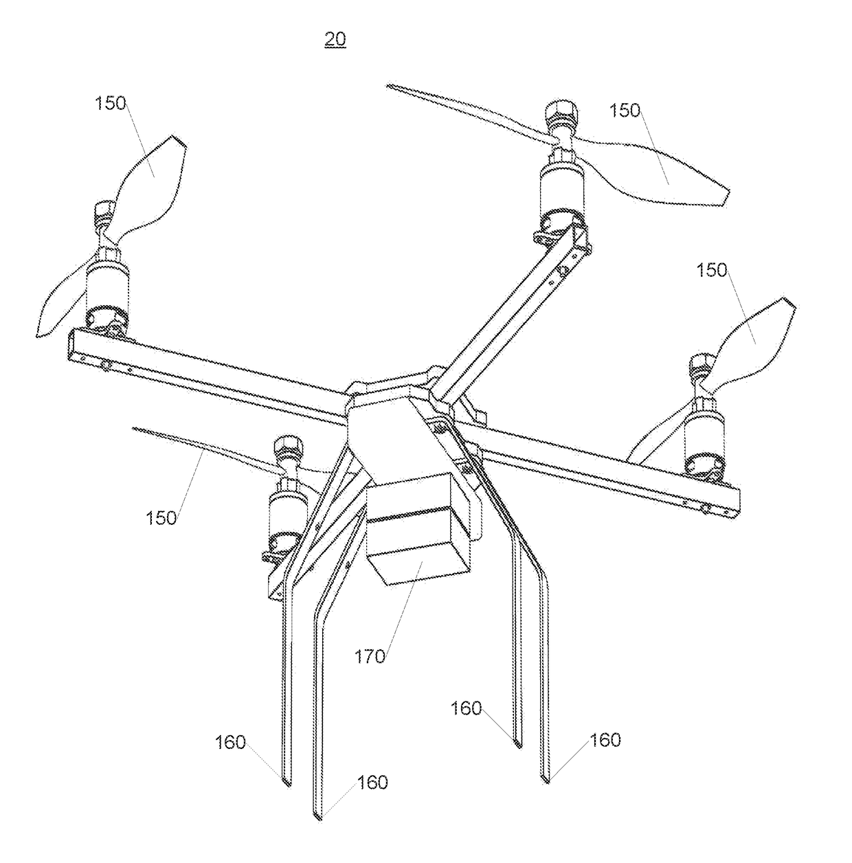
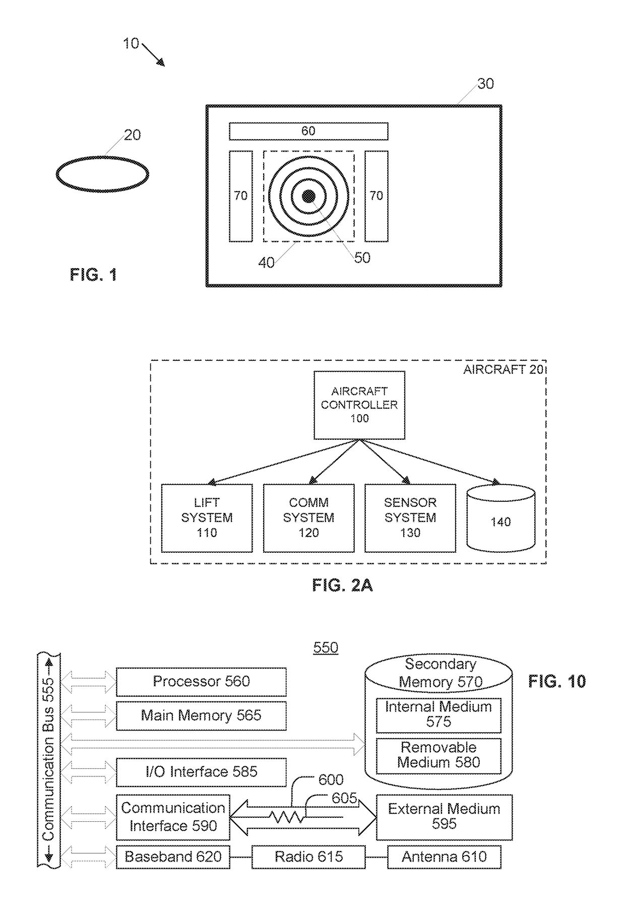
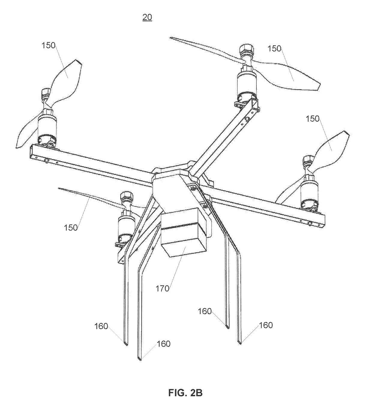
[0027]Certain embodiments disclosed herein provide for unmanned aircraft operation from a mobile structure including autonomous take off from the mobile structure and autonomous landing on the mobile structure. For example, one method disclosed herein allows for an unmanned aircraft to approach a mobile structure and identify a predetermined mobile landing area, determine a landing time corresponding to a desired attitude of the surface of the predetermined mobile landing area and then control operation of the lift system of the unmanned aircraft to bring the unmanned aircraft into contact with the surface of the mobile landing area. After reading this description it will become apparent to one skilled in the art how to implement the invention in various alternative embodiments and alternative applications. However, although various embodiments of the present invention will be described herein, it is understood that these embodiments are presented by way of example only, and not lim...


PUM


Abstract

Systems, apparatuses and methods for landing an unmanned aircraft on a mobile structure are presented. Sensors on the aircraft identify a predetermined landing area on a mobile structure. The aircraft monitors the sensor data to maintain its position hovering over the landing area. The aircraft estimates a future attitude of the surface of the landing area and determines a landing time that corresponds to a desired attitude of the surface of the landing area. The unmanned aircraft executes a landing maneuver to bring the aircraft into contact with the surface of the landing area at the determined landing time.

Description

RELATED APPLICATION[0001]The present application claims priority to U.S. provisional patent application No. 62 / 139,625 filed 27 Mar. 2015, which is incorporated herein by reference in its entirety.BACKGROUNDField of the Invention[0002]The present invention generally relates to unmanned aircraft and more specifically relates to autonomous takeoff and landing of an unmanned aircraft on a mobile structure.Related Art[0003]Unmanned aircraft were first used in military programs several decades ago. In military applications, unmanned aircraft systems are typically piloted by expertly trained operators under highly controlled conditions. More recently, unmanned aircraft are being used in civilian activities including both commercial and hobbyist activities. Today, multiple commercial uses for unmanned aircraft are being explored, with low levels of success because civilian unmanned aircraft are typically operated in a wide variety of conditions, by people with varying levels of skill. A si...

Claims


Application Information

Patent Timeline
IPC IPC(8): G05D1/06B64D45/04B64C39/02B64F1/12
CPCG05D1/0684B64D45/04B64C39/024B64F1/12G05D1/0669B64C2201/205B64C2201/208B64C2201/206B64C2201/18B64C2201/027B64C2201/108B64C2201/141B64D45/00G01C21/20B64U80/84B64U80/82B64U80/86B64U70/40B64U30/20B64U70/30B64U70/93B64U80/30B64U70/99B64U10/13B64U60/50B64U80/50B64U70/95B64U2201/10
Inventor TWINING, DAVID MERRICKWELLS, JOSHUA
Owner AEROVIRONMENT INC
Learn More