Resist removing apparatus and method for removing resist

a resist and apparatus technology, applied in the direction of electrical equipment, basic electric elements, semiconductor/solid-state device manufacturing, etc., can solve the problems of resist not being sufficiently removed, unable to adjust the distance between the surface of the main portion and the supply surface of the nozzle within the range of 1.0 mm or less, and the removal rate and in-plane uniformity decrease, so as to improve the removal rate and in-plane uniformity, the effect of removing the resis

Active Publication Date: 2018-06-21
MITSUBISHI ELECTRIC CORP
View PDF2 Cites 0 Cited by
  • Summary
  • Abstract
  • Description
  • Claims
  • Application Information

AI Technical Summary

Benefits of technology

[0008]It is an object of the present invention to provide a resist removing apparatus and a method for removing the resist that can improve a removal rate and an in-plane uniformity upon removal of a resist formed on a surface of a main portion of a sectional recession wafer and can sufficiently remove the resist.
[0010]The resist removing apparatus of the present invention has the characteristic above, so that the supply surface can be disposed in the close distance of less than or equal to 1.0 mm, for example, to face the surface of the main portion of the wafer having the protruding peripheral portion. Thus, when the ozone solution is supplied from the supply opening to remove the resist from the surface of the main portion, the removal rate and the uniformity upon the removal of the resist can be improved.
[0012]The method for removing a resist of the present invention includes the step (b) of disposing the supply surface in the close distance of less than or equal to 1.0 mm from the surface of the main portion of the wafer having the protruding peripheral portion and the step (c) of removing the resist from the surface of the main portion, so that the removal rate and the uniformity of the resist can be improved at the time of performing the step (c).

Problems solved by technology

Therefore, in a case where the conventional resist removing apparatus is used to remove the resist formed on the surface of the main portion of the sectional recession wafer inside the protruding peripheral portion, the protruding peripheral portion (height of approximately 0.725 mm) makes it substantially impossible to adjust the distance between the surface of the main portion and the supply surface of the nozzle within the range of 1.0 mm or less.
Consequently, the distance between the surface of the main portion of the sectional recession wafer and the supply surface of the nozzle inevitably exceeds 1.0 mm in the conventional resist removing apparatus, resulting in a decrease in the removal rate and in-plane uniformity upon the removal of the resist formed on the surface of the main portion of the sectional recession wafer.
This leads to the problem that the resist cannot be sufficiently removed.

Method used


Image

  • Resist removing apparatus and method for removing resist
  • Resist removing apparatus and method for removing resist

Examples


first preferred embodiment

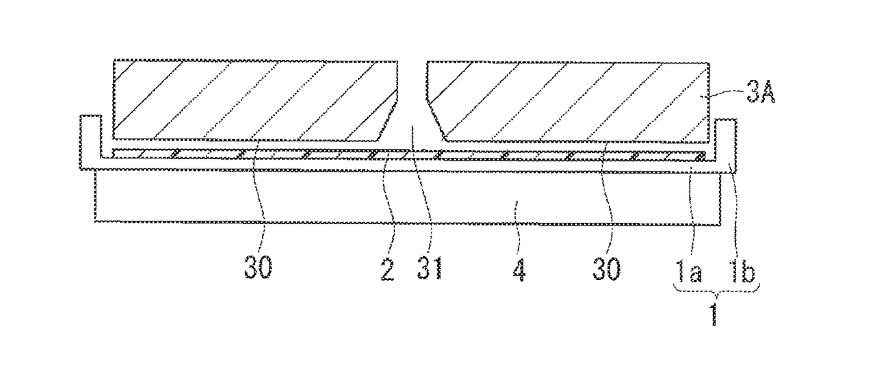
[0023]FIG. 1 is a cross-sectional view showing a structure of a nozzle of a resist removing apparatus according to a first preferred embodiment of the present invention. The resist removing apparatus of the first preferred embodiment includes a nozzle 3A having an optimal structure for removing the resist 2 formed on the surface of the wafer main portion 1a of the sectional recession wafer 1.

[0024]The structure of the nozzle 3A will be specifically described below. To supply ozone water being one of ozone solutions, the nozzle 3A has a tapered structure in cross section in the center thereof that expands outwardly from the center down from the middle, and the nozzle 3A also has, as the bottom, a supply surface 30 provided with a supply opening 31 that is circular in plan view.

[0025]The nozzle 3A as a whole is formed into the substantially cylindrical structure having the supply surface 30 with the supply opening 31 as the bottom surface. The supply surface 30 is slightly narrower th...

second preferred embodiment

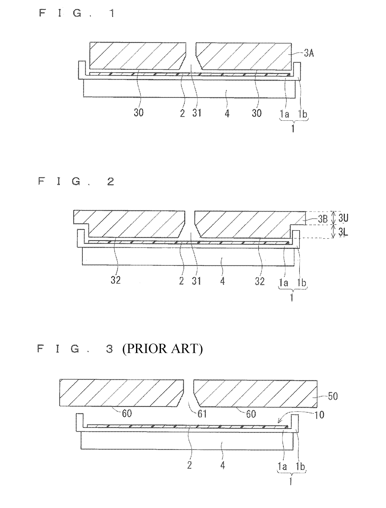
[0036]FIG. 2 is a cross-sectional view showing a structure of a nozzle of a resist removing apparatus according to a second preferred embodiment of the present invention. The resist removing apparatus of the second preferred embodiment includes a nozzle 3B having an optimal structure for removing the resist 2 formed on the surface of the wafer main portion 1a of the sectional recession wafer 1.

[0037]The structure of the nozzle 3B will be specifically described below. The nozzle 3B has, as the bottom, a supply surface 32 provided with the supply opening 31 for the ozone water in the center of the supply surface 32.

[0038]The nozzle 3B has a lower portion 3L formed in a cylindrical structure that has the supply surface 32 with the supply opening 31 as the bottom surface similarly to the nozzle 3A. The supply surface 32 similar to the supply surface 30 of the first preferred embodiment is narrower than the surface of the wafer main portion 1a and also has a shape that fits in the surfac...


PUM


Abstract

A nozzle as a whole is formed into a cylindrical structure having a supply surface with a supply opening as a bottom surface, and the supply surface is narrower than a surface of a wafer main portion of a sectional recession wafer and has a shape that fits in the surface of the wafer main portion. Therefore, in a state where the center of the wafer main portion and the center of the supply surface coincide with each other in plan view, the nozzle is brought close to the surface of the wafer main portion of the sectional recession wafer, whereby the supply surface of the nozzle can be disposed in a close distance from the surface of the wafer main portion in a wafer inner space.

Description

CROSS REFERENCE TO RELATED APPLICATIONS[0001]This application is a Divisional Application of U.S. patent application Ser. No. 14 / 614,990, filed on Feb. 5, 2015, which claims priority to and the benefit of Japanese Patent Application No. 2014-107763, filed on May 26, 2014, the entire contents of which all are incorporated herein by reference.BACKGROUND OF THE INVENTIONField of the Invention[0002]The present invention relates to an apparatus for removing a resist of a semiconductor wafer and a method for removing the resist.Description of the Background Art[0003]In the conventional resist removing apparatus that removes a resist formed on a surface of a semiconductor wafer with a nozzle for supplying an ozone solution such as ozone water, the nozzle is structured to have a supply surface having a shape wider than the surface of the semiconductor wafer to reliably cover the entire surface of the semiconductor wafer, and a distance between the supply surface of the nozzle and the surfac...

Claims


Application Information

Patent Timeline
Patent Type & Authority Applications(United States)
IPC IPC(8): H01L21/67H01L21/02
CPCH01L21/6708H01L21/67023H01L21/02057H01L21/67126
Inventor SAEKI, HISAYUKI
Owner MITSUBISHI ELECTRIC CORP
Why Eureka
Try Eureka