Power tool and transmission shaft assembly thereof

Active Publication Date: 2018-06-28
NANJING CHERVON IND
View PDF23 Cites 12 Cited by
  • Summary
  • Abstract
  • Description
  • Claims
  • Application Information

AI Technical Summary

Problems solved by technology

During operation of currently known long-rod type power tools, it is easy to g

Method used


Image

  • Power tool and transmission shaft assembly thereof
  • Power tool and transmission shaft assembly thereof
  • Power tool and transmission shaft assembly thereof

Examples


Embodiment Construction

[0017]The following description of the preferred embodiments is merely exemplary in nature and is in no way intended to limit the scope of the invention hereinafter claimed, its application, or uses.

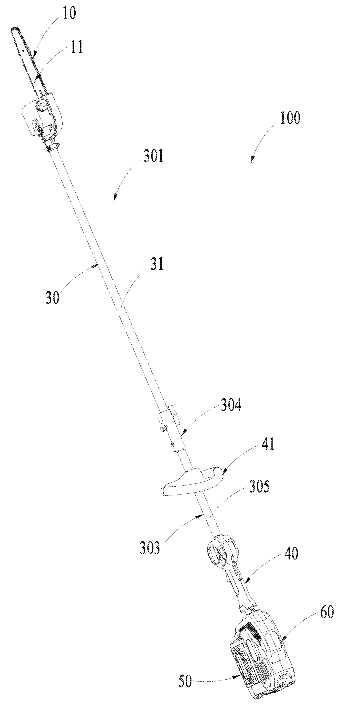
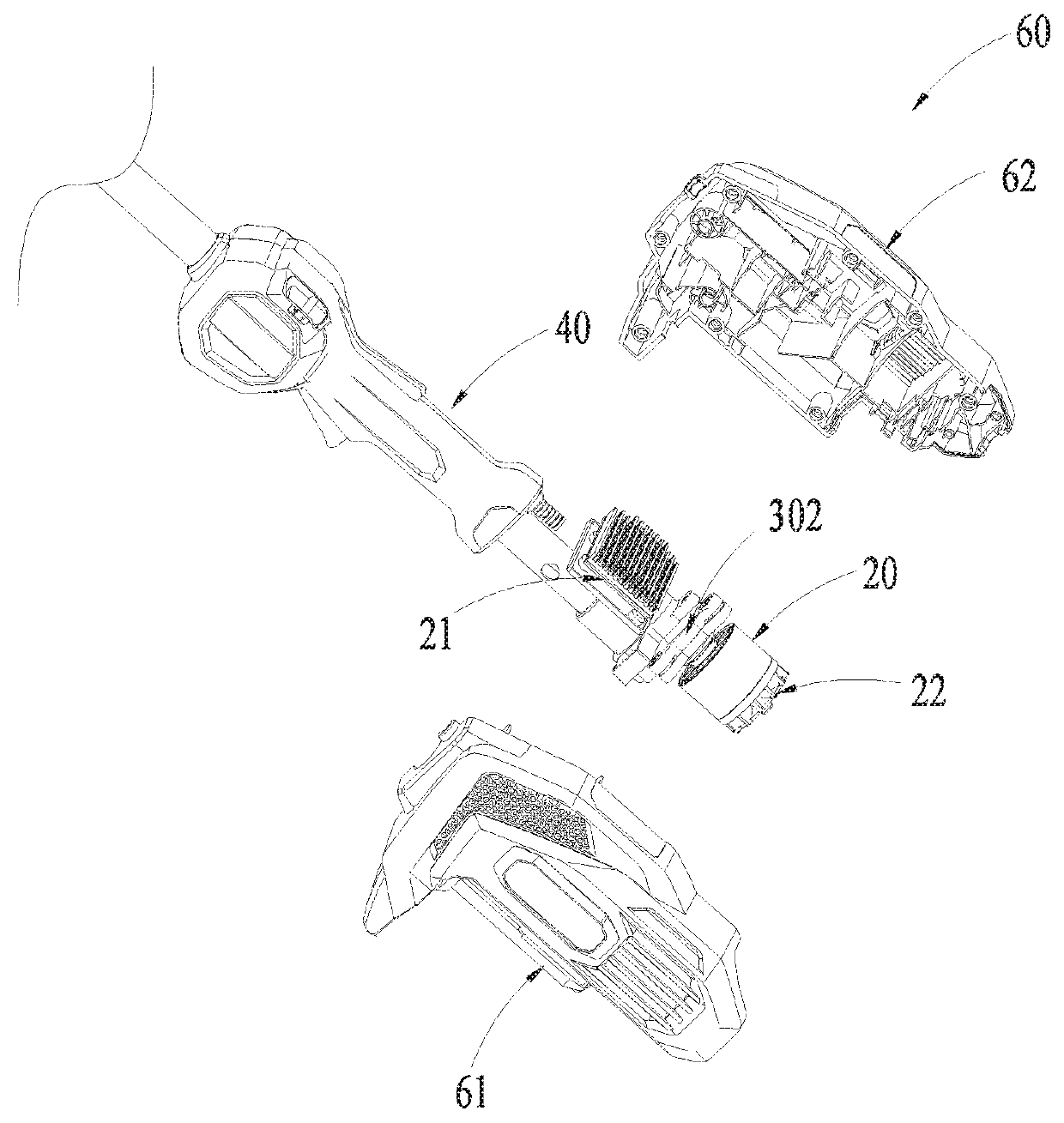
[0018]Referring to FIGS. 1-2, a power tool 100 includes a work attachment 10, a motor 20, a transmission device 301 and a main handle 40.

[0019]The work attachment 10 for performing the function of the tool is driven by the motor 20. The motor 20 can be an inner combustion engine powered by burning fuel or an electric motor powered by electricity. Specifically, the motor 20 is an electric motor. The power tool 100 further includes a battery pack 50 for supplying power to the motor 20 which is connected with the motor 20 electrically. The power tool 100 is an electric power tool. The transmission device 301 is connected with the motor 20 and the work attachment 10 to transmit the power of the motor 20 to the work attachment 10. The main handle 40 is for a user to grip, which is disposed be...


PUM


Abstract

A transmission shaft assembly includes a connecting tube extended along a central axis, a transmission shaft being a rigid shaft made of metal material, which is extended along the central axis and disposed in the connecting tube, a first limiting element disposed on an end of the connecting tube and formed with a first hole allowing the transmission shaft to pass there through, a second limiting element disposed on the other end of the connecting tube and formed with a second hole allowing the transmission shaft to pass there through, and a bushing. The bushing includes a main body formed with a channel extended along the central axis and several projecting parts disposed on the periphery of the main body. The bushing is located in the connecting tube and disposed between the first limiting element and the second limiting element. The transmission shaft passes through the first hole, the channel, and the second hole successively.

Description

RELATED APPLICATION INFORMATION[0001]This application claims the benefit under 35 U.S.C. §119(a) of Chinese Patent Application No. CN 201621434047X, filed on Dec. 23, 2016, the disclosure of which is incorporated herein by reference in its entirety.FIELD OF THE DISCLOSURE[0002]The present disclosure relates generally to a power tool and a transmission shaft assembly thereof.BACKGROUND OF THE DISCLOSURE[0003]Pole saws, grass trimmers and hedge trimmers with extension handles belong to long-rod type power tools with a long connecting rod. A motor and a work attachment are disposed on two ends of the connecting rod. A transmission shaft is disposed in the connecting rod.[0004]During operation of currently known long-rod type power tools, it is easy to generate vibration in the connecting rod because of the long transmission shaft.[0005]The statements in this section merely provide background information related to the present disclosure and may not constitute prior art.SUMMARY[0006]In ...

Claims


Application Information

Patent Timeline
IPC IPC(8): A01G3/053F16C3/02A01G3/06B25F5/02
CPCA01G3/053F16C3/02A01G3/062B25F5/02F16H3/64B25F5/001A01G3/086
Inventor FU, HUIXING
Owner NANJING CHERVON IND
Why Eureka
Try Eureka