Method for emissions plume monitoring in additive manufacturing

a technology of additive manufacturing and emissions plume, which is applied in the field of additive manufacturing apparatus and methods for monitoring emissions plume, can solve the problems of reducing beam intensity, affecting the build process, and affecting the quality of the produ

Active Publication Date: 2018-06-28
GENERAL ELECTRIC CO
View PDF2 Cites 34 Cited by
  • Summary
  • Abstract
  • Description
  • Claims
  • Application Information

AI Technical Summary

Benefits of technology

[0007]this problem is addressed by a method of using one or more sensors to provide a real-time understanding of the emissions plume trajectories in an additive manufacturing process.
[0008]According to one aspect of the technology described herein, a method is provided of monitoring an additive manufacturing process in which one

Problems solved by technology

The presence of the condensate can have detrimental effects on the build process, for example blockage of the energy beam, or a reduction in beam in

Method used


Image

  • Method for emissions plume monitoring in additive manufacturing
  • Method for emissions plume monitoring in additive manufacturing
  • Method for emissions plume monitoring in additive manufacturing

Examples


Embodiment Construction

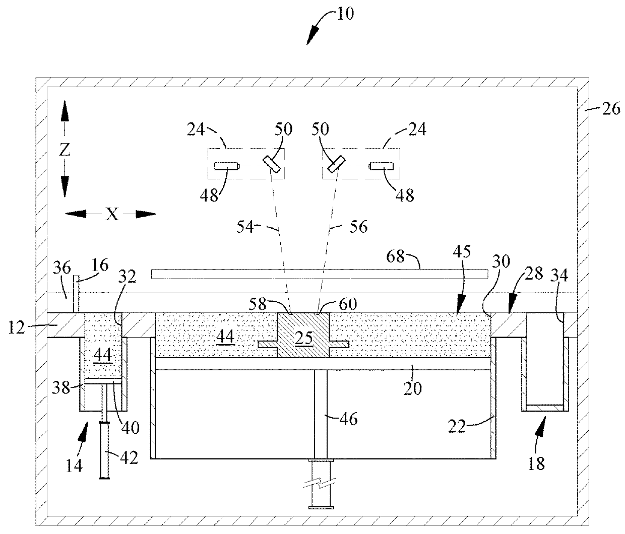
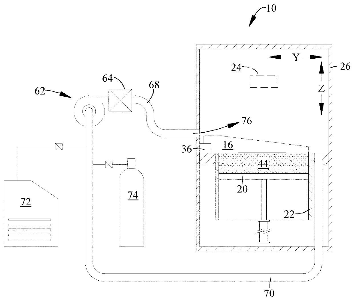
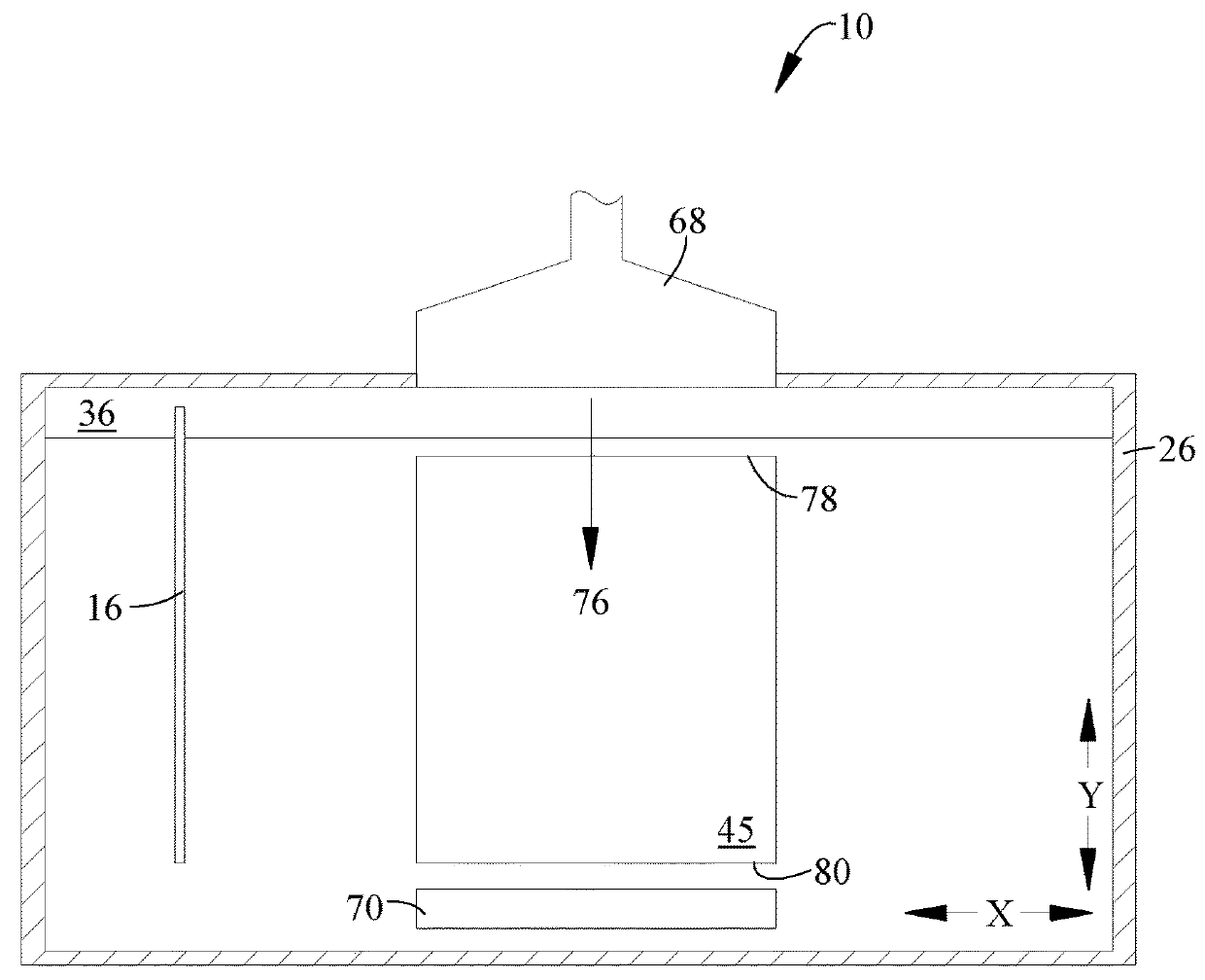
[0016]Referring to the drawings wherein identical reference numerals denote the same elements throughout the various views, FIG. 1 illustrates schematically an additive manufacturing machine 10 suitable for carrying out an additive manufacturing method. Basic components of the machine 10 include a table 12, a powder supply 14, a recoater 16, an overflow container 18, a build platform 20 surrounded by a build chamber 22, and at least one beam generator 24, all surrounded by a housing 26. Each of these components will be described in more detail below.

[0017]The table 12 is a rigid structure defining a planar worksurface 28. The worksurface 28 is coplanar with and defines a virtual workplane. In the illustrated example it includes a build opening 30 communicating with the build chamber 22 and exposing the build platform 20, a supply opening 32 communicating with the powder supply 14, and an overflow opening 34 communicating with the overflow container 18.

[0018]The recoater 16 is a rigi...


PUM

PropertyMeasurementUnit
Poweraaaaaaaaaa
Energyaaaaaaaaaa
Trajectoryaaaaaaaaaa

Abstract

A method of monitoring an additive manufacturing process in which one or more energy beams are used to selectively fuse a powder to form a workpiece, in the presence of one or more plumes generated by interaction of the one or more energy beams with the powder. The method includes using at least one sensor to generate at least one signal representative of a trajectory of one or more of the plumes.

Description

BACKGROUND OF THE INVENTION[0001]This invention relates generally to additive manufacturing, and more particularly to apparatus and methods for monitoring an emissions plume in additive manufacturing.[0002]Additive manufacturing is a process in which material is built up layer-by-layer to form a component. Additive manufacturing is also referred to by terms such as “layered manufacturing,”“reverse machining,”“direct metal laser melting” (DMLM), and “3-D printing”. Such terms are treated as synonyms for purposes of the present invention.[0003]One type of additive manufacturing machine is referred to as a “powder bed” machine and includes a build chamber that encloses a mass of powder which is selectively fused by a radiant energy beam to form a workpiece. The build chamber is enclosed in a housing that typically includes provisions for a flow of shielding gas therein. The shielding gas is used to transfer heat away from the surface of the powder bed, to prevent vaporized powder from ...

Claims


Application Information

Patent Timeline
IPC IPC(8): B22F3/105B33Y10/00B33Y50/02B23K26/342B23K26/70B23K26/042
CPCB22F3/1055B33Y10/00B33Y50/02B23K26/342B22F2203/03B23K26/042B22F2003/1057B22F2998/10B23K26/70B23K15/0086B23K15/0093B23K26/0006B23K26/03B23K26/0604B23K26/0643B23K26/127B23K26/14B23K26/082B22F2999/00B29C64/153B29C64/393B29C64/371Y02P10/25B22F10/28B22F12/90B22F12/70B22F10/322B22F12/45B22F10/80B22F10/32B22F12/67B22F10/77B22F12/44B22F10/85
Inventor MARTIN, ANDREW J.REDDING, MACKENZIE RYANMAMRAK, JUSTIN
Owner GENERAL ELECTRIC CO
Why Eureka
Try Eureka