Driver signal control circuit for display panel and display panel

Active Publication Date: 2018-06-28
TCL CHINA STAR OPTOELECTRONICS TECH CO LTD
View PDF2 Cites 1 Cited by
  • Summary
  • Abstract
  • Description
  • Claims
  • Application Information

AI Technical Summary

Benefits of technology

[0007]A driver signal control circuit for a display panel is proposed by a preferred embodiment of the present disclosure. The present disclosure aims to solve problems about one-side drivi

Problems solved by technology

In other words, the resistance of the resistor R1 is constantly changing during the process of fabricating the display panels in batches, which resulting in the production costs of the

Method used


Image

  • Driver signal control circuit for display panel and display panel
  • Driver signal control circuit for display panel and display panel

Examples


Example

[0019]For better understanding embodiments of the present disclosure, the following detailed description taken in conjunction with the accompanying drawings is provided. Apparently, the accompanying drawings are merely for some of the embodiments of the present invention. Any ordinarily skilled person in the technical field of the present invention could still obtain other accompanying drawings without use laborious invention based on the present accompanying drawings.

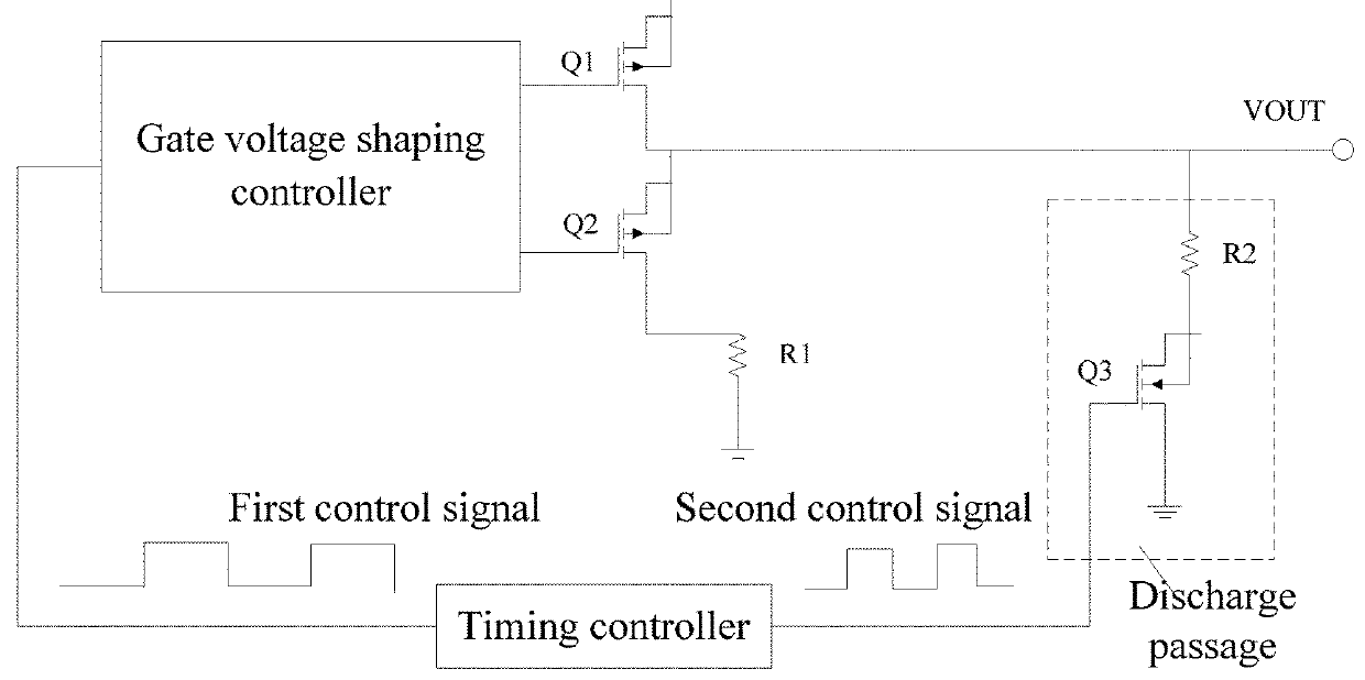
[0020]FIG. 2 is a circuit diagram illustrating a driver signal control circuit for a display panel according to a preferred embodiment of the present disclosure.

[0021]The driver signal control circuit comprises a timing controller, a gate voltage shaping controller, a first field-effect transistor (FET) Q1, a second FET Q2, a first resistor R1, and a discharge passage.

[0022]For example, the input terminal VIN of the control circuit receives the display driver signal from a display driver signal transmit unit. The displ...


PUM


Abstract

A driver signal control circuit for a display panel is proposed. A timing controller is connected to an input terminal of a gate voltage shaping controller and a first FET. A first output terminal of the gate voltage shaping controller is connected to a gate of the first FET. A drain of the first FET is connected to the output terminal of the control circuit. A second output terminal of the gate voltage shaping controller is connected to a gate of the second FET, and a source of the second FET is connected to the output terminal of the control circuit. A second terminal of the discharge passage is connected to an output terminal of the control circuit. The control circuit effectively prevents the production costs when display panels with different production batches are fabricated using different fabrication processes.

Description

BACKGROUND1. Field of the Disclosure[0001]The present disclosure relates to the field of signal processing technology, and more particularly, to a driver signal control circuit for a display panel and a display panel with the driver signal control circuit.2. Description of the Related Art[0002]One-side driving and both-side driving methods are adopted by a conventional display panel. With respect to the one-side driving method, a display driver signal is transmitted to one side of the display panel (such as the left side of the display panel) for most of time. Because of the RC delay in the display panel, the display effect on the left side of the display panel is different from the display effect on the right side.[0003]To enhance the display effect of the display panel adopting the one-side driving method, a display driver signal supplied to the display panel undergoes the chamfer process in the conventional technology. Accordingly, the problem that a shot mura appears on the pane...

Claims


Application Information

Patent Timeline
IPC IPC(8): G09G3/20
CPCG09G3/2092G09G2310/08G09G2310/0251G09G3/20G09G3/3266G09G3/3677
Inventor LI, WENFANGCAO, DAN
Owner TCL CHINA STAR OPTOELECTRONICS TECH CO LTD
Why Eureka
Try Eureka