
Drawer rail and home appliance including the same

a technology for home appliances and drawers, applied in the direction of household cleaners, tableware washing/rinsing machines, other angling devices, etc., can solve the problems of not being able to mount or separate the basket to or from the second rail, the movement of the item accommodation unit may not be realized smoothly and stably, and the dish arrangement is more difficult to arrange in the basket, so as to improve the reliability, the effect of easy engagement or disengagemen

Active Publication Date: 2018-07-05
LG ELECTRONICS INC
View PDF3 Cites 1 Cited by
  • Summary
  • Abstract
  • Description
  • Claims
  • Application Information

AI Technical Summary

Benefits of technology

The present invention provides a drawer rail that is easier to engage and disengage from a home appliance, and is more securely fixed to the appliance. The drawer rail also helps prevent noise from occurring between the home appliance and the drawer rail, by raising portions that limit backward movement of the drawer rail. This results in a more reliable and efficient drawer rail system.

Problems solved by technology

However, this structure has a shortcoming in that the distance that the item accommodation unit can move forwards and backwards is relatively short and in that, when the weight of the item accommodation unit increases, the movement of the item accommodation unit may not be realized smoothly and stably.
In the case in which the basket is disposed in the tub, it is more difficult to arrange the dishes in the basket.
However, it is not easy to mount or separate the basket to or from the second rail because the position of the second rail is not fixed.
However, it is not easy to mount or separate the drawer rail to or from the tub because the drawer rail is mounted inside the tub.

Method used


Image

  • Drawer rail and home appliance including the same
  • Drawer rail and home appliance including the same
  • Drawer rail and home appliance including the same

Examples


Embodiment Construction

[0083]Reference will now be made in detail to the preferred embodiments of the present invention, examples of which are illustrated in the accompanying drawings. Wherever possible, the same reference numbers will be used throughout the drawings to refer to the same or like parts.

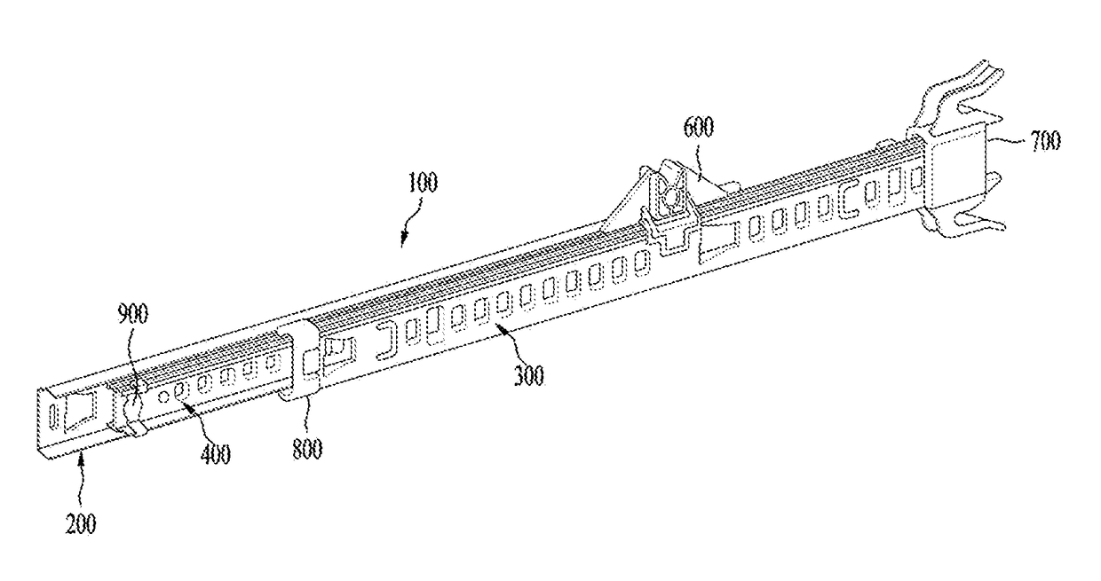
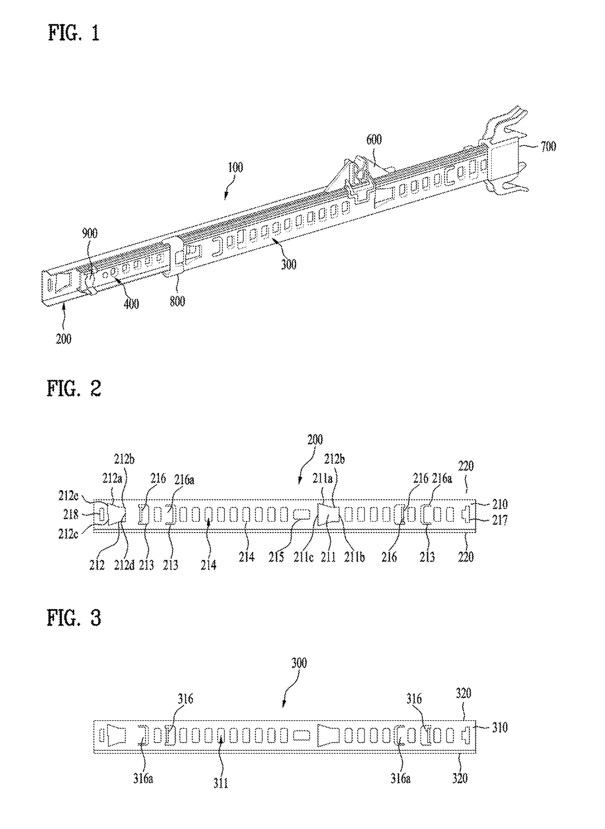
[0084]Hereinafter, a drawer rail will be described in brief with reference to FIG. 1. For convenience of explanation, a home appliance to which the drawer rail according to the embodiment is mounted will be described as being a dishwasher by way of example. However, the disclosure is not limited thereto.

[0085]The drawer rail 100 may include a first rail 200, a second rail 300, and a third rail 400.

[0086]The first rail 200 may be a fixed rail, which is fixed to a side wall of a storage chamber, for example, a side wall of a tub of the dishwasher. The second rail 300 may be a movable rail, which is coupled to an item accommodation unit, for example, a basket of the dishwasher. That is, the first rail 200 is fi...


PUM


Abstract

A drawer rail and a home appliance including the same are disclosed. The home appliance includes a drawer rail configured to withdraw an item accommodation unit provided in a storage chamber. The drawer rail includes a first rail mounted to the storage chamber, a second rail coupled to the item accommodation unit, a third rail disposed between the first rail and the second rail, a first retainer disposed between the first rail and the third rail to allow relative sliding movement, a second retainer disposed between the second rail and the third rail to allow relative sliding movement, a first stopper for limiting an allowable relative sliding distance between the first rail and the third rail, and a second stopper for limiting an allowable relative sliding distance between the second rail and the third rail.

Description

[0001]This application claims the benefit of Korean Patent Application No. 10-2017-0002098, filed on Jan. 5, 2017, which is hereby incorporated by reference as if fully set forth herein.BACKGROUND OF THE INVENTIONField of the Invention[0002]The present invention relates to a drawer rail and a home appliance including the same.Discussion of the Related Art[0003]Generally, a home appliance, such as a refrigerator, a dishwasher, etc., includes a drawer, a shelf or a basket in order to accommodate items therein. Such an item accommodation unit is provided so as to be movable forwards and backwards. For example, the item accommodation unit of a dishwasher is a basket. A user may draw out the basket by pulling the same to put or take dishes in or out of the basket. Thereafter, the user may push the basket into the dishwasher.[0004]The movement of an item accommodation unit in the forward-and-backward direction may be realized by various structures. For example, a rail groove may be formed...

Claims


Application Information

Patent Timeline
Patent Type & Authority Applications(United States)
IPC IPC(8): A47B88/57A47L15/50A47B88/437
CPCA47B88/57A47L15/507A47B88/437A47B2210/17A47B2210/0032A47B2088/4278A47B2088/401A47B88/493A47B88/477A01K97/06
Inventor MIN, HYESEONG
Owner LG ELECTRONICS INC
Learn More