
Footplate structure of wheelchair

Inactive Publication Date: 2018-07-05
KYMCO
View PDF1 Cites 1 Cited by
  • Summary
  • Abstract
  • Description
  • Claims
  • Application Information

AI Technical Summary

Benefits of technology

The present invention offers a footplate control unit that can be used with a footplate unit on a wheelchair to improve its operation. This unit can be set at an upright or horizontal position to enhance the wheelchair's performance.

Problems solved by technology

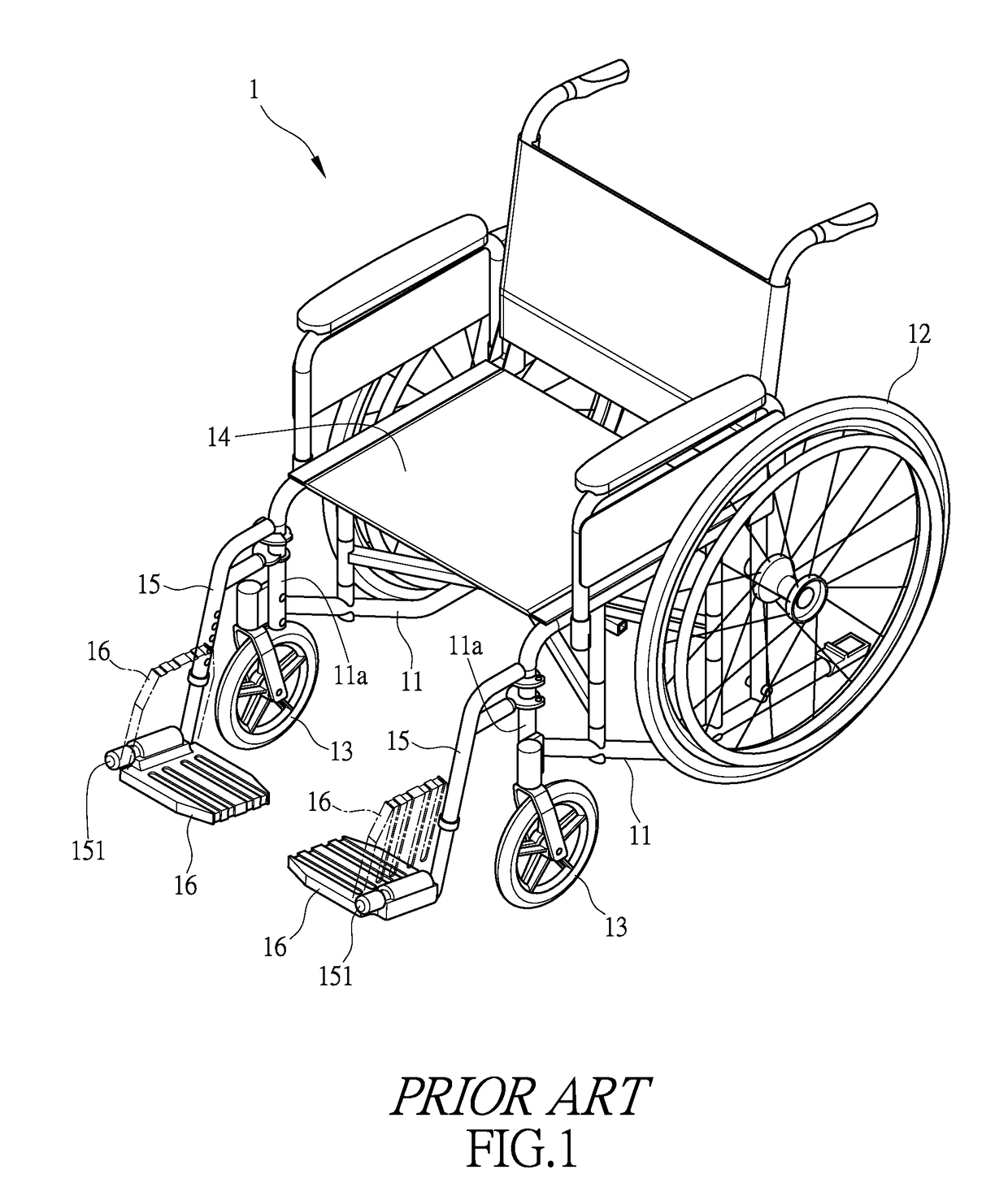
The user or an attendant, when attempting to use a hand to pull and rotate the footplates 16, is subject to potential risk of contamination.
Thus, it is a challenge of the manufacturers of wheelchair to provide a footplate structure of a wheelchair, which makes rotation of footplates easy.

Method used


Image

  • Footplate structure of wheelchair
  • Footplate structure of wheelchair
  • Footplate structure of wheelchair

Examples


Embodiment Construction

[0018]The following descriptions are exemplary embodiments only, and are not intended to limit the scope, applicability or configuration of the invention in any way. Rather, the following description provides a convenient illustration for implementing exemplary embodiments of the invention. Various changes to the described embodiments may be made in the function and arrangement of the elements described without departing from the scope of the invention as set forth in the appended claims.

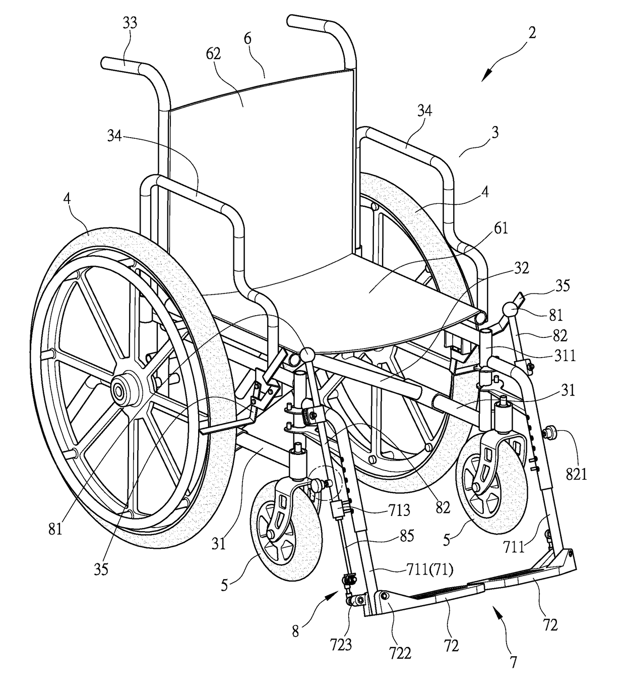
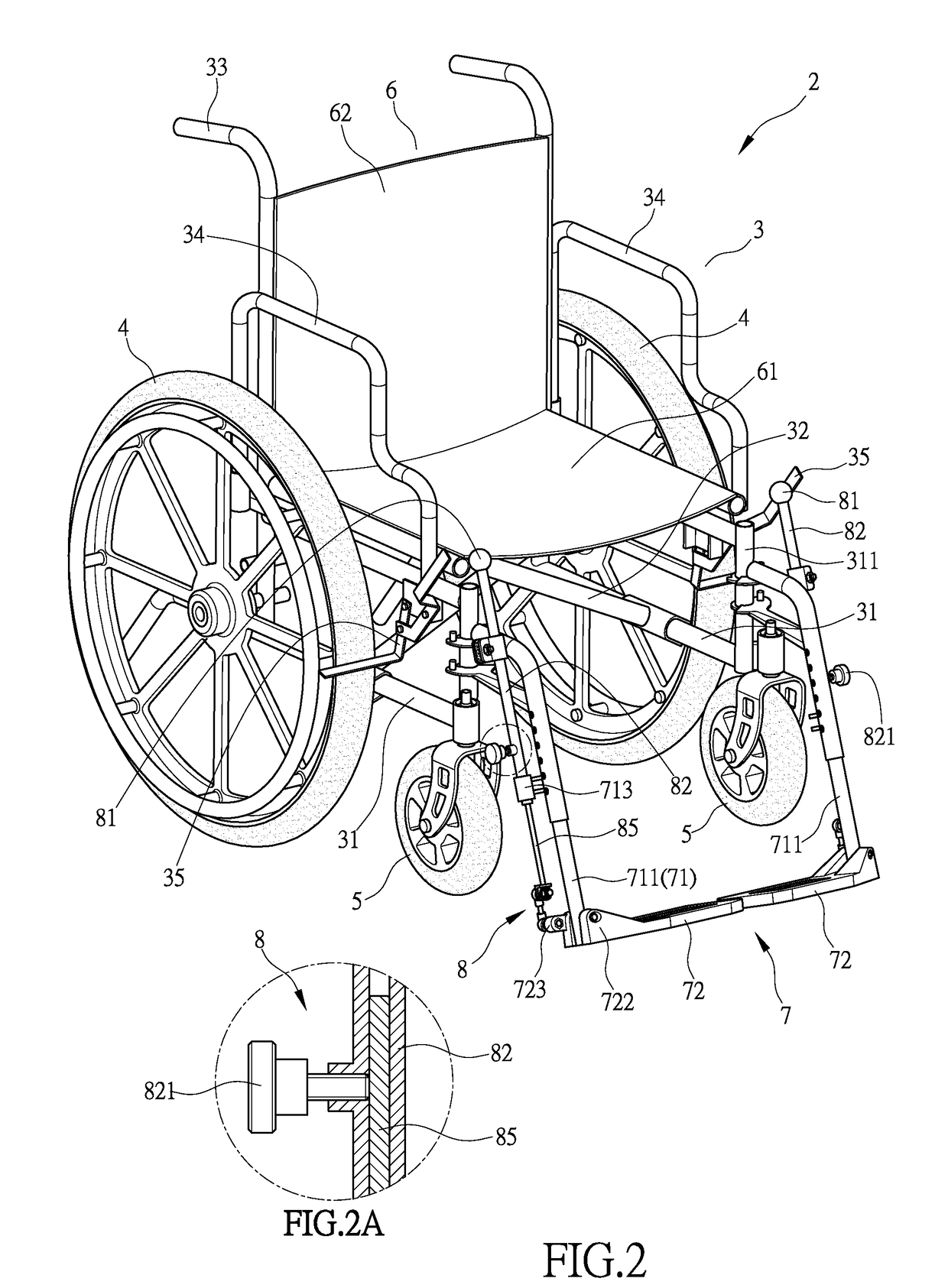
[0019]Firstly, referring to FIG. 2, the present invention provides a footplate structure of a wheelchair. The wheelchair 2 comprises a support frame unit 3, rear wheel assemblies 4 arranged at a rear side of the support frame unit 3, front wheel assemblies 5 arranged at a front side of the support frame unit 3, a seat unit 6 arranged at a center of the support frame unit 3, a footplate unit 7 arranged at a front end of the support frame unit 3, and a footplate control unit 8 that controls the footpl...


PUM


Abstract

A footplate structure of a wheelchair is provided. The wheelchair includes a support frame unit, a rear wheel assembly mounted on the support frame unit, a front wheel assembly mounted to the support frame unit, a seat unit arranged at a central portion of the support frame unit, a footplate unit arranged at a front end of the support frame unit, and a footplate control unit operable to control the footplate unit. With the footplate control unit set beside the footplate unit, the footplate control unit may control a footplate of the footplate unit to be in an upright position or a horizontal position so as to improve operation performance of the wheelchair.

Description

(a) TECHNICAL FIELD OF THE INVENTION[0001]The present invention relates to a footplate structure of a wheelchair, and more particularly to a footplate structure of the wheelchair that facilitates controllability of a footplate unit of the wheelchair.(b) DESCRIPTION OF THE PRIOR ART[0002]As shown in FIG. 1, to facilitate outdoor activity or transportation of a limb disabled person, a wheelchair 1 is often used to provide assistance. The wheelchair 1 is provided, a pair of left and right rear wheels 12 and a pair of left and right front wheels 13 respectively set at two sides of a support frame unit 11. The support frame unit 11 is provided, at a central portion thereof, with a seat unit 14. The support frame unit 11 is provided, on a front end 11a thereof, with a pair of left and right footplate support racks 15. The footplate support racks 15 are each provided with a pivot pin 151, and the pivot pin 151 rotatably supports a footplate 16, so that the footplate 16 is allowed to freely...

Claims


Application Information

Patent Timeline
IPC IPC(8): A61G5/12
CPCA61G5/128A61G2203/00A61G2200/34A61G5/1054A61G5/101
Inventor CHEN, YI-TSO
Owner KYMCO
Learn More