Electronic device and fan control method
- Summary
- Abstract
- Description
- Claims
- Application Information
AI Technical Summary
Benefits of technology
Problems solved by technology
Method used
Image
Examples
Embodiment Construction
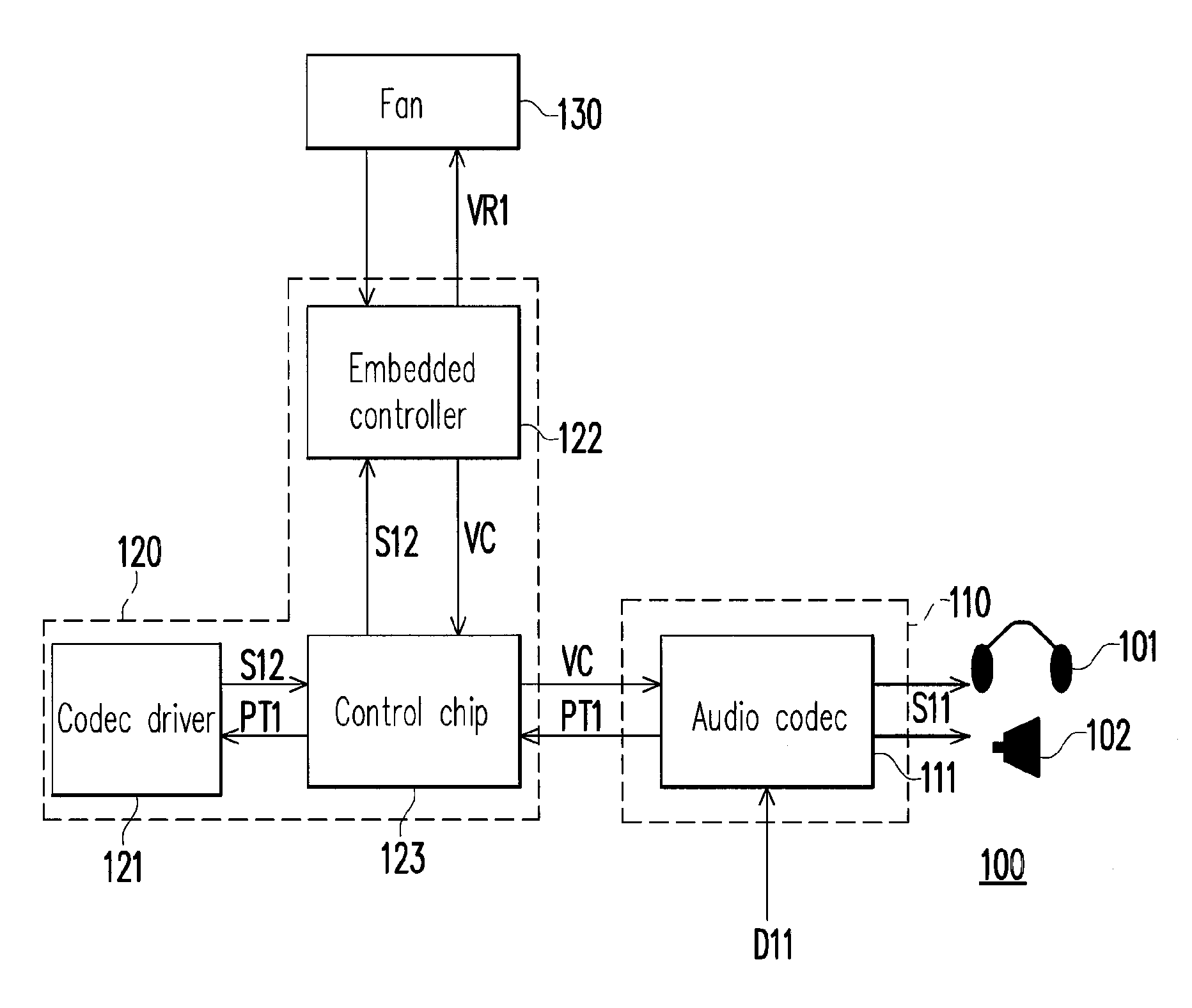
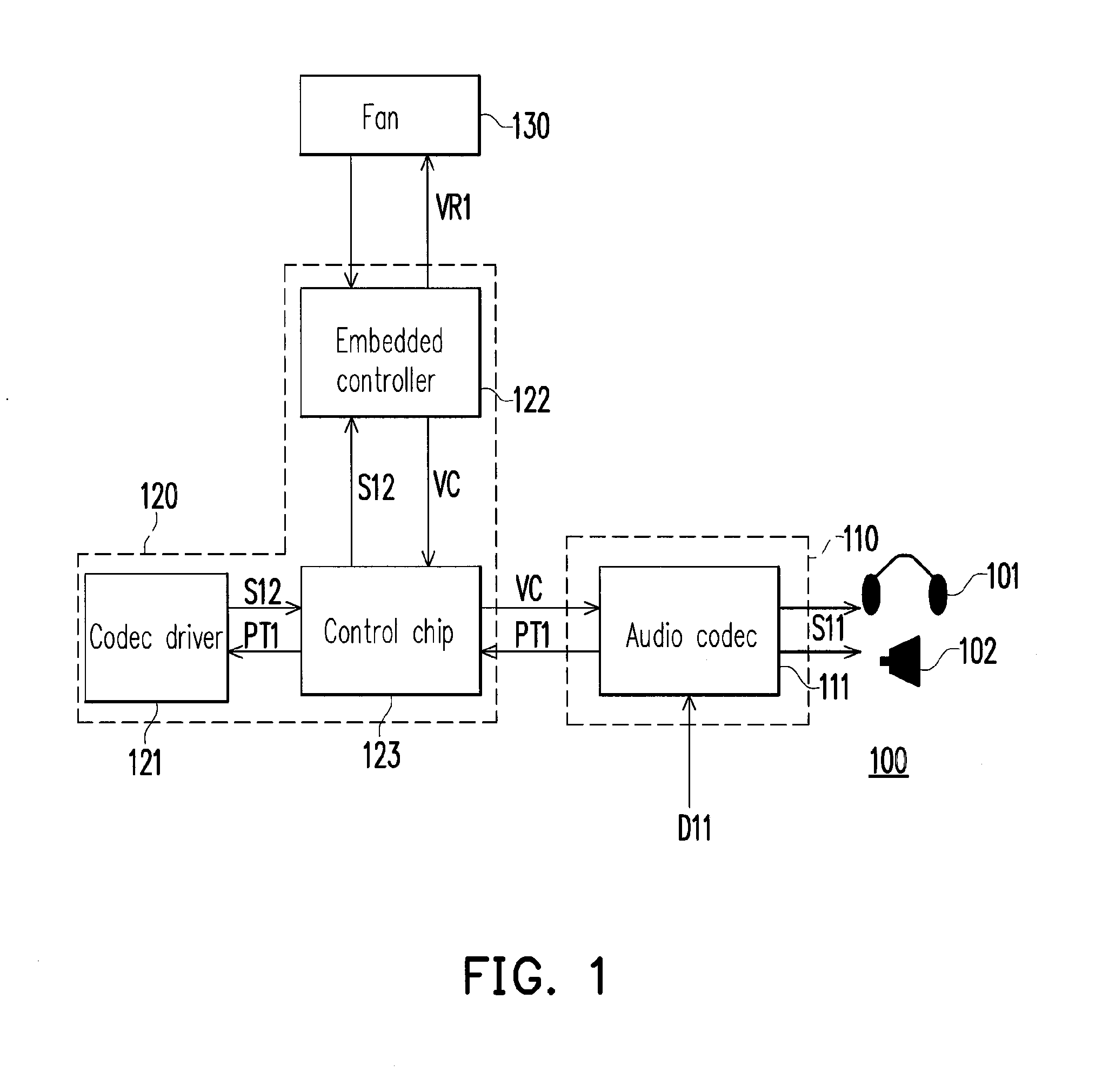
[0024]FIG. 1 is a block schematic diagram of an electronic device according to an embodiment of the invention. Referring to FIG. 1, the electronic device 100 includes an audio module 110, a monitoring module 120 and a fan 130. The audio module 110 is electrically connected to a play device, for example, an earphone 101 or an inbuilt speaker 102. Moreover, the monitoring module 120 is electrically connected to the audio module 110 and the fan 130.
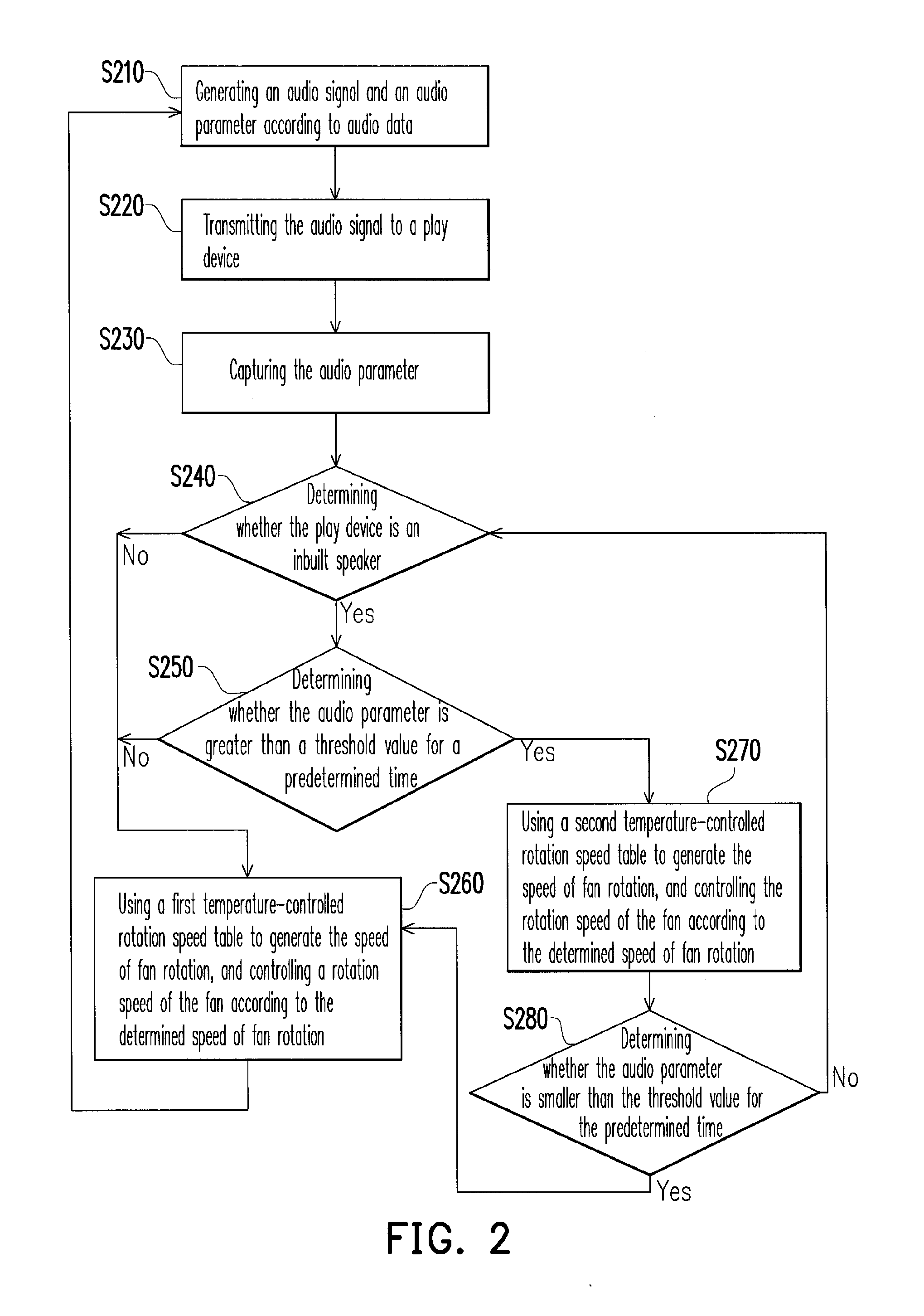
[0025]In operation, the audio module 110 generates an audio signal S11 and an audio parameter PT1 according to audio data D11. Moreover, the audio module 110 transmits the audio signal S11 to the play device, and the play device accordingly produces a corresponding sound. On the other hand, the monitoring module 120 determines to use a first temperature-controlled rotation speed table or a second temperature-controlled rotation speed table to generate a speed VR1 of fan rotation according to a type of the play device and the audio parameter ...
PUM
 Abstract
Description
Claims
Application Information
 - R&D
- Intellectual Property
- Life Sciences
- Materials
- Tech Scout
- Unparalleled Data Quality
- Higher Quality Content
- 60% Fewer Hallucinations
Browse by: Latest US Patents, China's latest patents, Technical Efficacy Thesaurus, Application Domain, Technology Topic, Popular Technical Reports.
© 2025 PatSnap. All rights reserved.Legal|Privacy policy|Modern Slavery Act Transparency Statement|Sitemap|About US| Contact US: help@patsnap.com


