Needleless syringe

a syringe and needleless technology, applied in the field of needleless syringes, can solve the problems of injection solution being discharged in an unintended state, injection solution being discharged erroneously, and diaphragm being unintentionally depressed

Active Publication Date: 2018-07-05
DAICEL CHEM IND LTD
View PDF4 Cites 0 Cited by
  • Summary
  • Abstract
  • Description
  • Claims
  • Application Information

AI Technical Summary

Benefits of technology

[0008]In order to solve the problems as described above, the present disclosure resides in a syringe for discharging an injection objective substance (for example, an injection solution) without using any injection needle, wherein the voltage application, which is performed with respect to a driving unit, is correlated with an injection operation performed by a user, i.e., the operation, in which a discharge port of the syringe is brought in contact with an injection target area in order to perform the injection by the user, is mechanically correlated with the voltage application which performed with respect to the driving unit. Accordingly, the execution of a series of operations performed by the user in order to carry out the injection is an requirement to permit the discharge of the injection objective substance. Therefore, it is possible for the user to precisely avoid any unintended discharge of the injection objective substance.
[0027]It is possible to appropriately avoid the unintended discharge from the syringe which discharges the injection objective substance such as the injection solution or the like without using any injection needle.

Problems solved by technology

On this account, if the combustion of the propellant is performed on account of any erroneous operation of the user, there is a possibility that the injection solution may be discharged in an unintended state.
That is, for example, when the user removes the safety member in order to use the syringe, then the diaphragm may be unintentionally depressed, and the injection solution may be erroneously discharged.

Method used


Image

  • Needleless syringe
  • Needleless syringe
  • Needleless syringe

Examples


first embodiment

1>

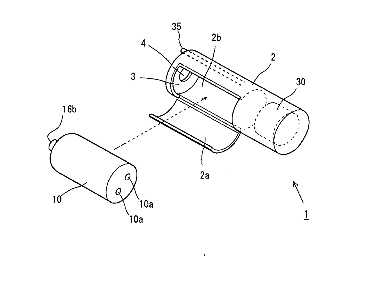
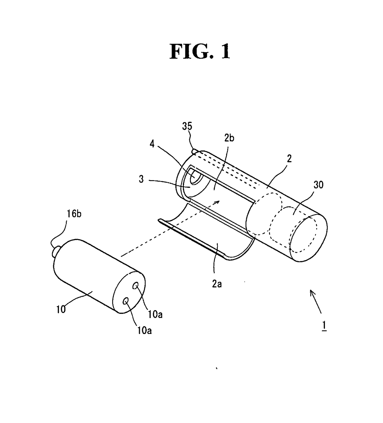
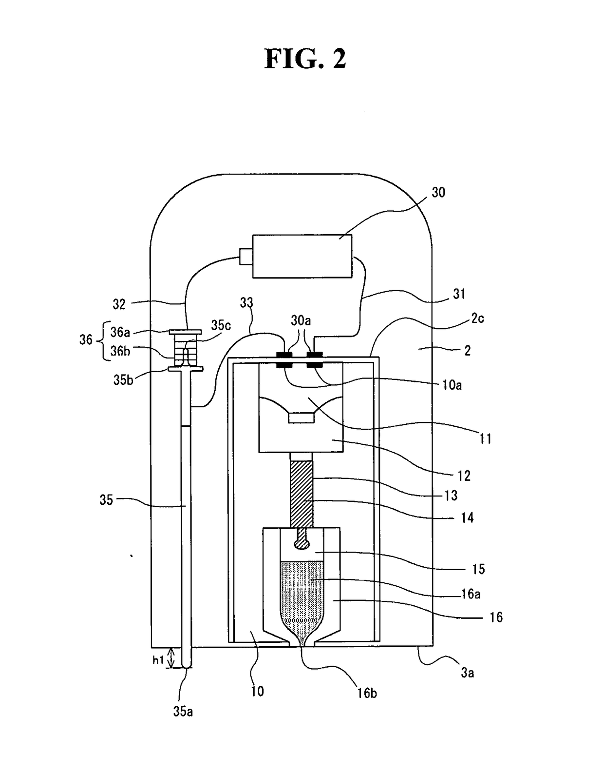
[0042]In this specification, FIGS. 1 and 2 shows a schematic structure of the syringe 1. FIG. 1 shows a perspective view illustrating the syringe 1, and FIG. 2 shows a sectional view of the syringe 1 taken in a longitudinal direction thereof. The syringe 1 is formed by charging a syringe unit 10 described later on into a housing 2. Note that, in the following description of this specification, the injection objective substance, which is injected into an injection target area by the syringe 1, is generally referred to as “injection solution”. However, this does not intend to limit the content and the form of the substance to be injected. As for the injection objective substance, it is allowable that the component, which is to be delivered, for example, to the skin structure as the injection target area, is either dissolved or undissolved. Further, no problem arises in relation to the specified form of the injection objective substance as well, provided that the injection objective ...

first modified embodiment

[0059]A first modified embodiment of the syringe 1 will now be explained on the basis of FIGS. 4A and 4B. FIG. 4A shows front views illustrating syringes 1 as viewed from the forward end side. In the embodiment described above, as shown in FIG. 4A, one switch member 35 is arranged, which protrudes from the forward end surface 3a of the housing 2. However, in this modified embodiment, as shown in FIG. 4B, a plurality of, i.e., three switch members 35 are arranged at equal intervals (equal angles) around the center of the discharge port of the nozzle 16b. Note that the protruding heights of the respective switch members 35 are set to approximately identical heights. Further, three switch members 36, which correspond to the respective switch members 35, are arranged in the housing 2. Then, the three pairs of switch members 35, 36 are connected in series between the connecting terminal 30a and the plus terminal of the battery 30.

[0060]In the case of the syringe 1 according to this modif...

second modified embodiment

[0061]An explanation will now be made on the basis of FIGS. 5A-5C about a second modified embodiment of the syringe 1. The embodiment described above is constructed such that the spring portion 36b is arranged between the brim portion 35b of the switch member 35 and the brim portion 36a of the switch member 36, and the protruding state of the switch member 35 is maintained by the urging force exerted on the switch member 35. On the other hand, this modified embodiment adopts a structure to retain the protruding state in place of the spring portion 36b. Specifically, the protruding state is maintained by a maintaining member 6 which is fixed in the housing 2 and a columnar projecting portion 35d which is provided at a portion positioned at the inside of the housing 2 in a state in which the switch member 35 is not brought in contact with the injection target area (portion of the switch member 35 belonging to an area disposed on the left side with respect to a dotted line shown in FIG...


PUM


Abstract

The described technology relates to a needleless syringe for injecting an injection objective substance into an injection target area. The needleless syringe includes a protruding member which is provided movably from a first position to a second position at which 1) a protruding length of a forward end of the protruding member from an end surface of a housing is shorter than a protruding length of the forward end at the first position and 2) the forward end and a discharge port can be brought in contact with the injection target area. The needleless syringe also includes a maintaining mechanism which maintains the protruding member at the first position and a power source circuit which applies a voltage to a driving unit when the protruding member having been maintained at the first position is moved to the second position. Accordingly, the unintended discharge from the syringe is appropriately avoided.

Description

CROSS-REFERENCE TO RELATED APPLICATIONS[0001]This application is a continuation application, and claims the benefit under 35 U.S.C. §§ 120 and 365 of PCT Application No. PCT / JP2015 / 073068, filed on Aug. 18, 2015, which is hereby incorporated by reference.TECHNICAL FIELD[0002]The present disclosure relates to a needleless syringe with which an injection objective substance is injected into an injection target area without using any injection needle.BACKGROUND ART[0003]A syringe is known, with which an injection component is discharged or injected by utilizing the energy of a combustion gas produced by the ignition of a propellant or explosive. For example, in the case of a syringe described in Patent Literature 1, a current flows through a filament by supplying an ignition current from a battery to an ignition device, and an injection solution is discharged in accordance with the combustion of the propellant. The current supply from the battery is executed by a user by intruding or d...

Claims


Application Information

Patent Timeline
Patent Type & Authority Applications(United States)
IPC IPC(8): A61M5/30
CPCA61M5/30A61M2005/2013A61M5/315A61M5/3007
Inventor HAITSUKA, MASAHIROYAGI, TOSHIKI
Owner DAICEL CHEM IND LTD
Why Eureka
Try Eureka