Sputtering apparatus

a technology of sputtering apparatus and substrate, which is applied in the direction of vacuum evaporation coating, coating, electric discharge tube, etc., can solve the problem of generating a pollution source of the substra

Active Publication Date: 2016-06-14
CANON ANELVA CORP
View PDF10 Cites 0 Cited by
  • Summary
  • Abstract
  • Description
  • Claims
  • Application Information

AI Technical Summary

Benefits of technology

[0012]By using the present invention, unintended discharge between the cathode and the ground shield can be reduced in a highly efficient magnetron sputtering apparatus in which a ground shield made of a magnetic material is disposed on the outer circumference of a target.

Problems solved by technology

This abnormal discharge may cause a damage to the backing plate 7 or the fixation part 13, the inner side of the shield 14, or the like, and may resultantly generate a pollution source of a substrate.
Such a problem is particularly conspicuous in high frequency sputter with high ion density in a plasma.

Method used


Image

  • Sputtering apparatus
  • Sputtering apparatus
  • Sputtering apparatus

Examples


example

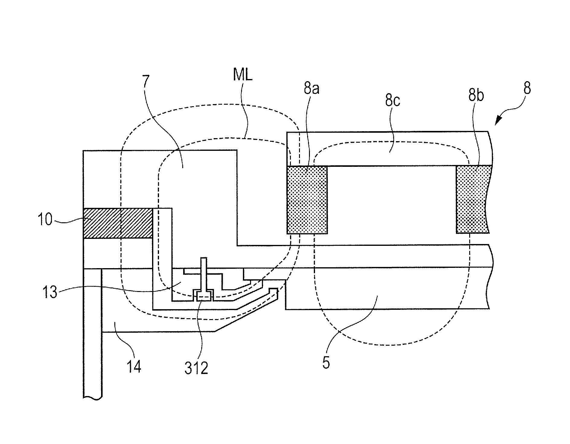
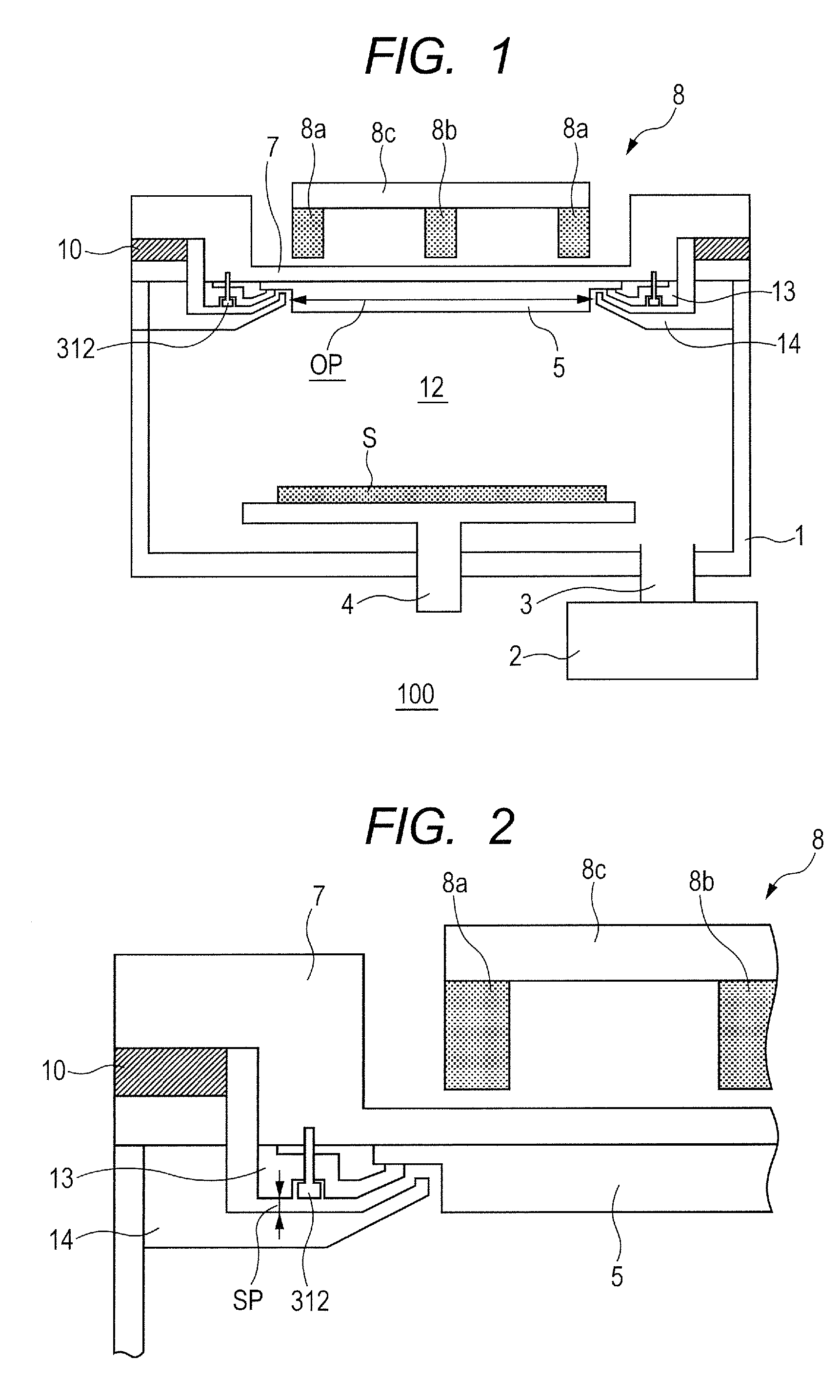
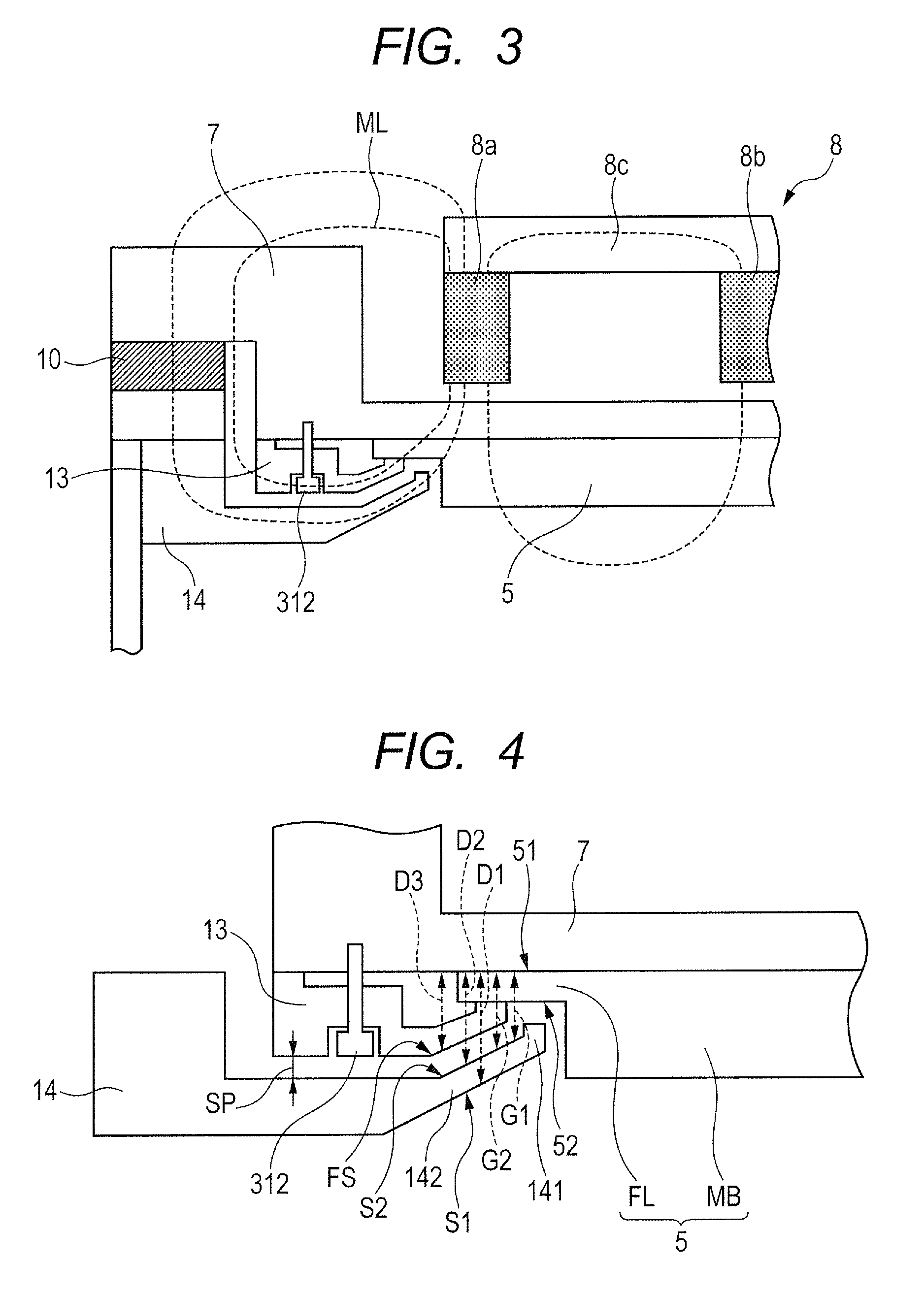
[0036]For the target 5, a target material may be used such as a pure metal (for instance, titanium) or an alloy (for instance, alloy of aluminum and copper), a magnetic material (for instance, Co), a dielectric material (for instance, SiO2), for instance. The target 5 is fixed to the backing plate 7 by the fixation part 13 so that the contact face of the target 5 comes into contact with the contact face of the backing plate 7. The backing plate 7 may be made of, for instance, a high thermally conductive material such as an oxygen-free copper. In the target 5, for instance, the outer diameter of the flange FL may be 180 mm, the thickness of the flange FL may be 3 mm, the outer diameter of the main body (to be sputtered portion) MB may be 160 mm, and the thickness of the main body MB may be 14 mm.

[0037]The fixation part 13 is made of SUS440C, for instance. An angle A (see FIG. 4) between the second inclined portion and a plane parallel to the contact face (this is typically parallel t...


PUM

PropertyMeasurementUnit
thicknessaaaaaaaaaa
thicknessaaaaaaaaaa
outer diameteraaaaaaaaaa

Abstract

The present invention provides a highly efficient magnetron sputtering apparatus in which a ground shield made of a magnetic material is disposed on the outer circumference of a target, the sputtering apparatus being capable of reducing unintended discharge between a cathode and the ground shield. The sputtering apparatus according to an embodiment includes: a backing plate connected to a power supply and having a target mounting surface; a magnet disposed on the back surface of the backing plate; a grounded shield containing a magnetic material and surrounding the target mounting surface; and a fixation part located between the shield and the backing plate at an outer circumference of the target mounting surface and serving as a magnetic member. This structure reduces magnetic field lines which pass through a space between the shield and the fixation part.

Description

CROSS-REFERENCES TO RELATED APPLICATIONS[0001]This application is a continuation application of International Application No. PCT / JP2013 / 006789, filed Nov. 19, 2013, which claims the benefit of Japanese Patent Application No. 2013-039310 filed Feb. 28, 2013. The contents of the aforementioned applications are incorporated herein by reference in their entireties.TECHNICAL FIELD[0002]The present invention relates to a sputtering apparatus.BACKGROUND ART[0003]In manufacturing of integrated circuits, display panels, disks and the like, sputtering (hereinafter also referred to as sputter) is widely used to form a film on a substrate such as a semiconductor wafer, a glass panel, and a resin disk. Sputter is a film formation technique in which ions collide with the surface of a target, and thereby particles are ejected from the surface and are deposited on a substrate to form a film. The target is fixed to a backing plate. The backing plate is cooled by a cooling means, thereby cooling the...

Claims


Application Information

Patent Timeline
Patent Type & Authority Patents(United States)
IPC IPC(8): H01J37/34C23C14/35H01J37/32
CPCC23C14/35H01J37/32651H01J37/3405H01J37/3417H01J37/3461H01J37/3441
Inventor SHINADA, MASATOUEDA, KEISUKE
Owner CANON ANELVA CORP
Why Eureka
Try Eureka