Power supply system

a power supply system and power supply technology, applied in the direction of charging stations, battery/fuel cell control arrangements, transportation and packaging, etc., to achieve the effect of preventing unintended power, prolonging travel distance, and preventing degradation of driving performan

Active Publication Date: 2022-09-22
HONDA MOTOR CO LTD
View PDF2 Cites 1 Cited by
  • Summary
  • Abstract
  • Description
  • Claims
  • Application Information

AI Technical Summary

Benefits of technology

[0012]The power supply system of the first aspect of the present invention connects the first power circuit having the first electrical storage device and the second power circuit having the second electrical storage device having a use voltage range relative to the closed circuit voltage that overlaps the first electrical storage device and a static voltage lower than the first electrical storage device by the voltage converter, and connects the first power circuit and the rotary electrical machine by the power converter. The power control unit controls the charge/discharge of the first electrical storage device and second electrical storage device by operating the power converter and voltage converter. Herein, in the case of wanting to inhibit or suppress discharge from the second electrical storage device for any reason, the power control unit operates the voltage converter and/or power converter so that all or a majority of the requested power for the rotary electrical machine is covered by the power outputted from the first electrical storage device. However, when electrical current flowing in the first electrical storage device increases, there are cases where the closed circuit voltage of the first electrical storage device becomes lower than the static voltage of the second electrical storage device, and unintended power is outputted from the second electrical storage device. To address this, the present invention acquires the first voltage parameter corresponding to the closed circuit voltage of the first electrical storage device by the first voltage parameter acquisition unit, acquires the second voltage parameter corresponding to the static voltage of the second electrical storage device by the second voltage parameter acquisition unit, and the power control unit then causes power to discharge from the second electrical storage device so that the second voltage parameter becomes no more than the first voltage parameter. Consequently, according to the present invention, it is possible to prevent that second electrical storage device from turning to unintended discharge by the static voltage of the second electrical storage device falling below the closed circuit voltage of the first electrical storage device.
[0013]In the second aspect of the present invention, with the electric vehicle traveling by way of the power of the aforementioned two such electrical storage devices, in the case of the system output upper limit made by combining the output upper limit of the first electrical storage device and the output upper limit of the second electrical storage device becoming less than a predetermined output threshold, it may set the remaining travelable distance as 0. In Japanese Patent Application No. 2020-061200 by the present applicant shows technology which, in a power supply system establishing the first electrical storage device as capacity type and the second electrical storage device as output type, prevents the output upper limit of the second electrical storage device from rapidly decreasing prior to using up the power stored in the first electrical storage device, and the remaining travelable distance suddenly dropping to 0. With this power supply system shown in Japanese Patent Applicat...

Problems solved by technology

However, when great power is requested by the drive motor as during acceleration, for example, the electrical current flowing in the first electrical storage de...

Method used


Image

  • Power supply system
  • Power supply system
  • Power supply system

Examples


Embodiment Construction

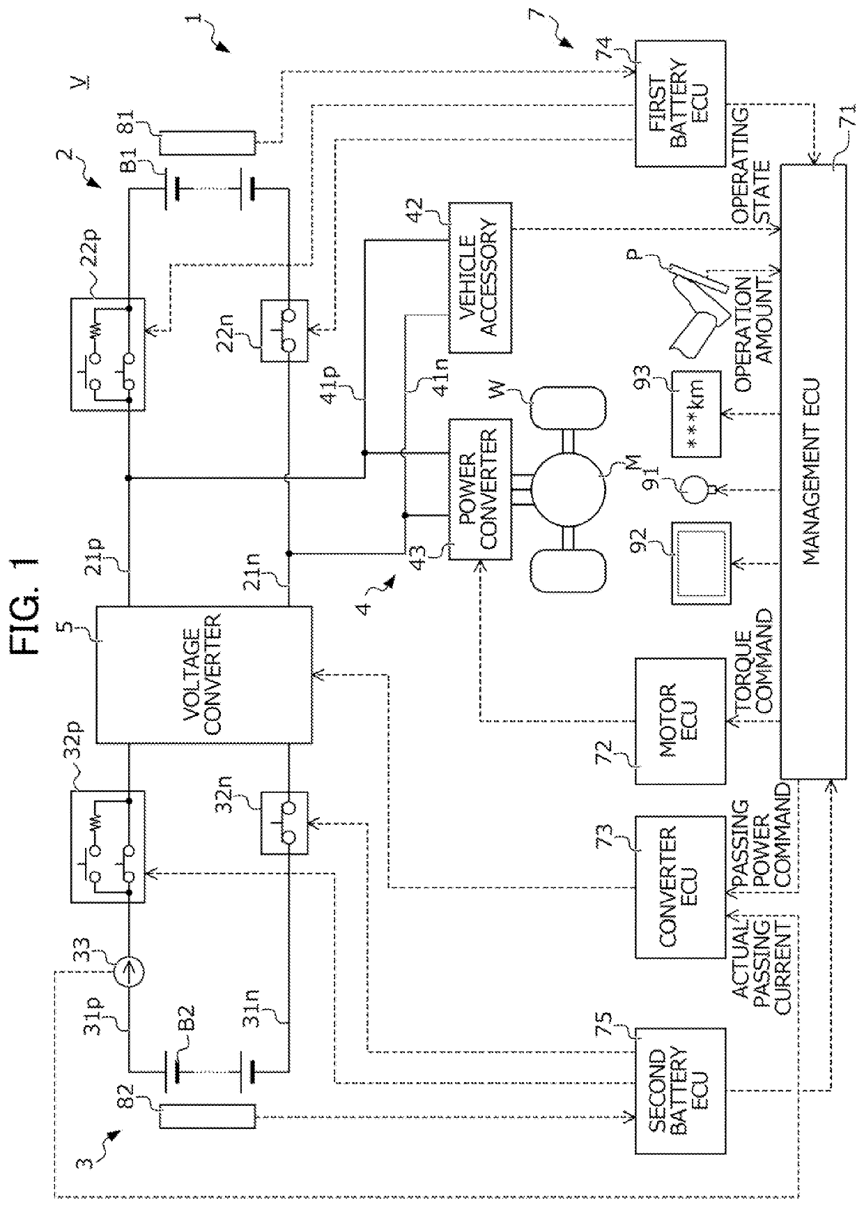
[0025]Hereinafter, an embodiment of the present invention will be explained while referencing the drawings. FIG. 1 is a view showing the configuration of an electric vehicle V (hereinafter simply referred to as “vehicle”) equipped with a power supply system 1 according to the present embodiment.

[0026]The vehicle V includes drive wheels W, a drive motor M serving as a rotary electrical machine coupled to these drive wheels W; and a power supply system 1 which performs transferring of power between this drive motor M and a first battery B1 and second battery B2 described later. It should be noted that the present embodiment explains an example in which the vehicle V accelerates and decelerates by the motive power generated mainly by the drive motor M; however, the present invention is not to be limited thereto. The vehicle V may be established as a so-called hybrid vehicle equipped with the drive motor M and an engine as the motive power generation source.

[0027]The drive motor M is co...


PUM


Abstract

A power supply system includes: a first power circuit having a first battery, a second power circuit having a second battery, a voltage converter which converts voltage between the first power circuit and the second power circuit, a power converter which converts power between the first power circuit and the drive motor, a power control unit which controls charge/discharge of the first and second batteries by operating the voltage converter and the power converter, a first voltage parameter acquisition unit which calculates an effective value for the closed circuit voltage of the first battery as a first voltage parameter, a second voltage parameter acquisition unit which calculates the static voltage of the second battery as a second voltage parameter, in which the power control unit causes power to discharge from the second battery so that the second voltage parameter becomes no more than the first voltage parameter.

Description

[0001]This application is based on and claims the benefit of priority from Japanese Patent Application No. 2021-046084, filed on 19 Mar. 2021, the content of which is incorporated herein by reference.BACKGROUND OF THE INVENTIONField of the Invention[0002]The present invention relates to a power supply system. In more detail, it relates to a power supply system for an electric vehicle including two electrical storage devices.Related Art[0003]In recent years, development has been active in electric vehicles such as electric transport equipment equipped with a drive motor as a power generation source, and hybrid vehicles equipped with a drive motor and internal combustion engine as power generation sources. In such electric vehicles, power supply devices such as an electrical storage device (battery, capacitor, etc.) and fuel cell for supplying electrical energy to the drive motor is also built in. In addition, in recent years, a vehicle equipped with a plurality of power supply device...

Claims


Application Information

Patent Timeline
IPC IPC(8): H02J7/00B60L53/20B60L58/18
CPCH02J7/007182B60L53/20B60L58/18H02J7/0013H02J7/0048H02J7/0063H02J2207/20H02P27/08B60L58/10B60L58/14B60L58/15H02M3/1584H02P4/00B60L58/13B60L58/16B60L2240/545B60L7/10B60L58/20B60L2240/547H02J7/1423H02J7/1446H02J7/1492H02J2310/48H02M3/158
Inventor NAGASAWA, MINORUOGUMA, HIROKAZUOHISHI, ARATAYAMADA, YASUOKANAMARU, YOSHIHIRO
Owner HONDA MOTOR CO LTD
Why Eureka
Try Eureka