Image capturing assembly, imaging apparatus and electronic device

a technology of image capturing and assembly, applied in the field of image capturing assembly and imaging apparatus, can solve the problems of unfavorable portability requirements, difficult to reduce and miniaturize the size of the lens assembly, and conventional optical systems cannot meet the current technology development trend

Active Publication Date: 2018-07-05
LARGAN PRECISION
View PDF6 Cites 39 Cited by
  • Summary
  • Abstract
  • Description
  • Claims
  • Application Information

AI Technical Summary

Benefits of technology

[0008]According to one aspect of the present disclosure, an image capturing assembly includes six lens elements, the six lens elements being, in order from an object side to an image side, a first lens element, a second lens element, a third lens element, a fourth lens element, a fifth lens element and a sixth lens element. The first lens element has positive refractive power. The fourth lens element with positive refractive power has an image-side surface being convex. The fifth lens element has an object-side surface being convex. The sixth lens element has an image-side surface being concave, wherein the image-side surface of the sixth lens element includes at least one inflection point. When an Abbe number of the second lens element is V2, an Abbe number of the third lens element is V3, an Abbe number of the fifth lens element is V5, a central thickness of the first lens element is CT1, a central thickness of the third lens element is CT3, a focal length of the image capturing assembly is f, and a focal length of the third lens element is f3, the following conditions are satisfied:

Problems solved by technology

However, the size of lens assemblies being hard to reduce and miniaturize is a problem in general for photographing modules, which is a characteristic unfavorable for requirements of portables.
Thus, conventional optical systems cannot satisfy the developing trend of current technology.

Method used


Image

  • Image capturing assembly, imaging apparatus and electronic device
  • Image capturing assembly, imaging apparatus and electronic device
  • Image capturing assembly, imaging apparatus and electronic device

Examples


1st embodiment

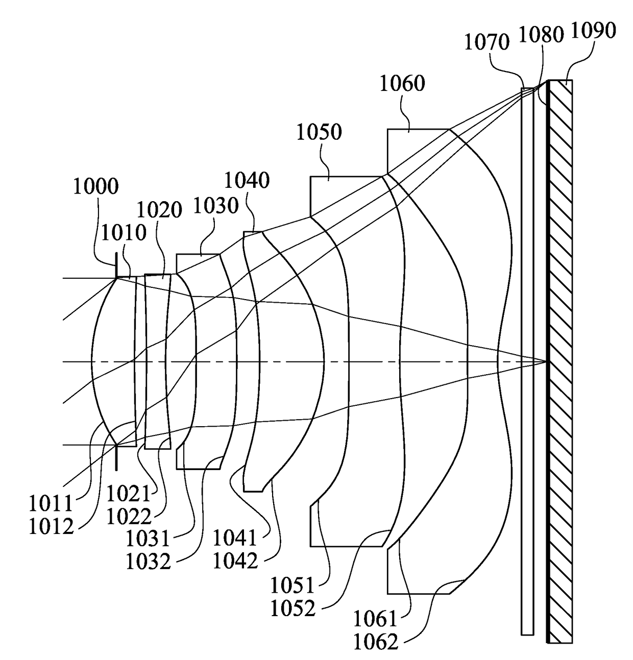
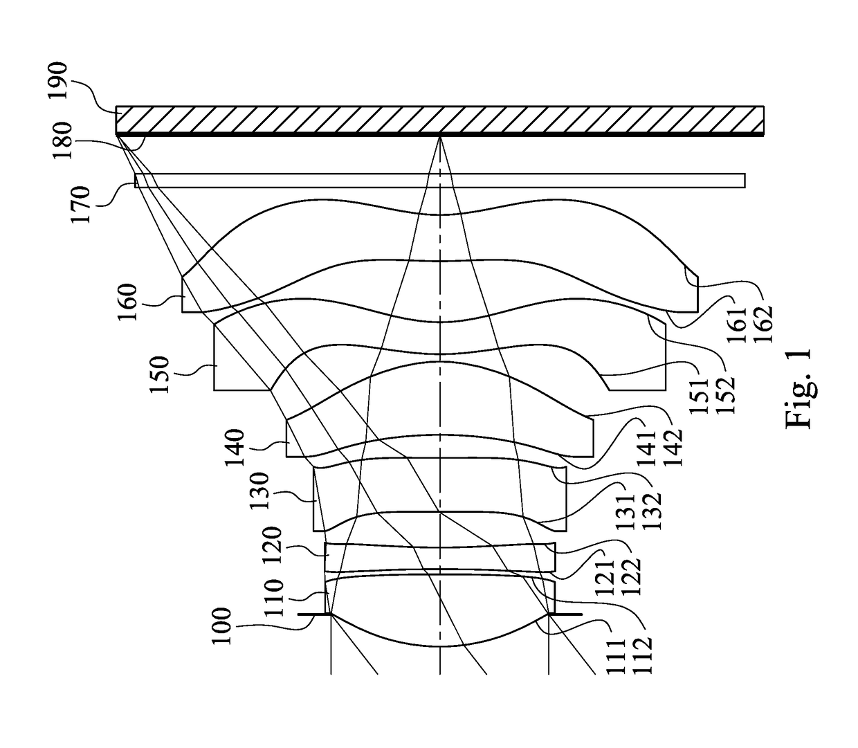
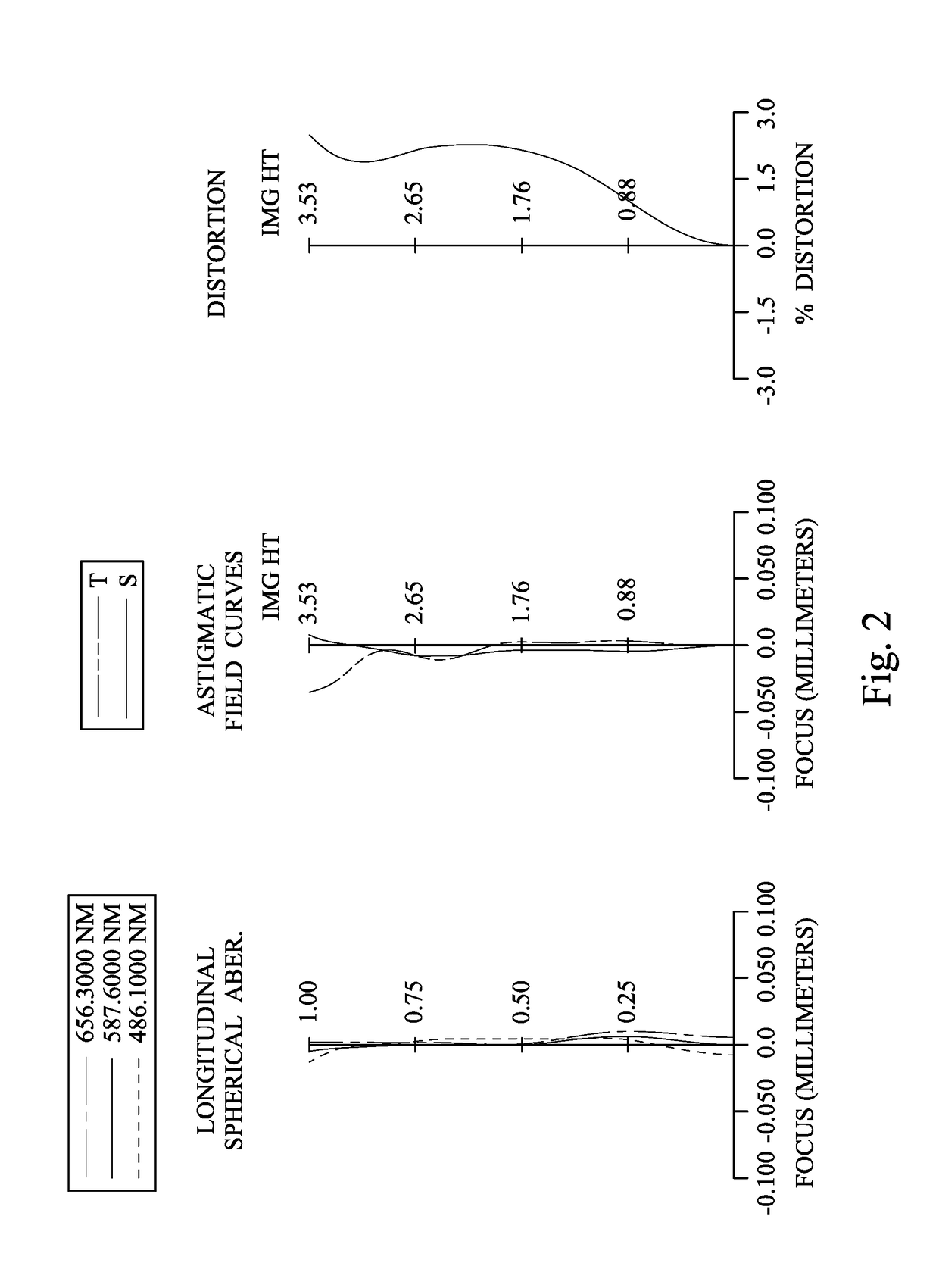
[0082]FIG. 1 is a schematic view of an imaging apparatus according to the 1st embodiment of the present disclosure. FIG. 2 shows spherical aberration curves, astigmatic field curves and a distortion curve of the imaging apparatus according to the 1st embodiment. In FIG. 1, the imaging apparatus includes an image capturing assembly (its reference numeral is omitted) and an image sensor 190. The image capturing assembly includes, in order from an object side to an image side, an aperture stop 100, a first lens element 110, a second lens element 120, a third lens element 130, a fourth lens element 140, a fifth lens element 150, a sixth lens element 160, a filter 170 and an image surface 180, wherein the image sensor 190 is disposed on the image surface 180 of the image capturing assembly. The image capturing assembly includes six lens elements (110, 120, 130, 140, 150, 160) without additional one or more lens elements inserted between the first lens element 110 and the sixth lens eleme...

2nd embodiment

[0111]FIG. 3 is a schematic view of an imaging apparatus according to the 2nd embodiment of the present disclosure. FIG. 4 shows spherical aberration curves, astigmatic field curves and a distortion curve of the imaging apparatus according to the 2nd embodiment. In FIG. 3, the imaging apparatus includes an image capturing assembly (its reference numeral is omitted) and an image sensor 290. The image capturing assembly includes, in order from an object side to an image side, a first lens element 210, an aperture stop 200, a second lens element 220, a third lens element 230, a fourth lens element 240, a fifth lens element 250, a sixth lens element 260, a filter 270 and an image surface 280, wherein the image sensor 290 is disposed on the image surface 280 of the image capturing assembly. The image capturing assembly includes six lens elements (210, 220, 230, 240, 250, 260) without additional one or more lens elements inserted between the first lens element 210 and the sixth lens eleme...

3rd embodiment

[0122]FIG. 5 is a schematic view of an imaging apparatus according to the 3rd embodiment of the present disclosure. FIG. 6 shows spherical aberration curves, astigmatic field curves and a distortion curve of the imaging apparatus according to the 3rd embodiment. In FIG. 5, the imaging apparatus includes an image capturing assembly (its reference numeral is omitted) and an image sensor 390. The image capturing assembly includes, in order from an object side to an image side, an aperture stop 300, a first lens element 310, a second lens element 320, a third lens element 330, a fourth lens element 340, a fifth lens element 350, a sixth lens element 360, a filter 370 and an image surface 380, wherein the image sensor 390 is disposed on the image surface 380 of the image capturing assembly. The image capturing assembly includes six lens elements (310, 320, 330, 340, 350, 360) without additional one or more lens elements inserted between the first lens element 310 and the sixth lens eleme...


PUM


Abstract

An image capturing assembly includes six lens elements, the six lens elements being, in order from an object side to an image side, a first lens element, a second lens element, a third lens element, a fourth lens element, a fifth lens element and a sixth lens element. The first lens element has positive refractive power. The fourth lens element with positive refractive power has an image-side surface being convex. The fifth lens element has an image-side surface being concave. The sixth lens element has an image-side surface being concave, wherein the image-side surface of the sixth lens element includes at least one inflection point.

Description

RELATED APPLICATIONS[0001]This application claims priority to Taiwan Application Serial Number 105143962, filed Dec. 29, 2016, which is herein incorporated by reference.BACKGROUNDTechnical Field[0002]The present disclosure relates to an image capturing assembly and an imaging apparatus. More particularly, the present disclosure relates to an image capturing assembly and an imaging apparatus with a compact size applicable to electronic devices.Description of Related Art[0003]With the wider application of photographing modules, installing photographing modules in various smart electronic devices, portables, mobile devices, recognition devices, entertainment systems, sporting devices and smart home assisting systems is becoming a major trend in developments for the future technology, especially portables which are in high public demands. In order to obtain more extensive experiences in utilizations, smart devices with one, two or more than three lens assemblies are becoming the market ...

Claims


Application Information

Patent Timeline
Patent Type & Authority Applications(United States)
IPC IPC(8): G02B13/00G02B9/62
CPCG02B13/0045G02B9/62G02B13/06G02B13/18
Inventor HSIEH, TUNG-YILIN, CHENG-CHENHSUEH, CHUN-CHECHEN, CHUN-YENHUANG, HSIN-HSUAN
Owner LARGAN PRECISION
Why Eureka
Try Eureka