Zoom lens and imaging apparatus

a zoom lens and imaging apparatus technology, applied in the field of zoom lenses, can solve the problems of large lens diameter, difficult to achieve both wide angle and size reduction, and achieve the effect of reducing size and weight and high optical performan

Active Publication Date: 2018-07-05
FUJIFILM CORP
View PDF1 Cites 3 Cited by
  • Summary
  • Abstract
  • Description
  • Claims
  • Application Information

AI Technical Summary

Benefits of technology

[0006]The present invention has been made in consideration of the above-mentioned situations, it is an object of the present invention to provide a zoom lens, for which reduction in size and weight is achieved while wide angle is achieved and which has high optical performance throughout the entire zoom range, and an imaging apparatus comprising the zoom lens.
[0033]According to the present invention, the zoom lens consists of, in order from the object side, a first lens group that has a positive refractive power and remains stationary during zooming, a plurality of movable lens groups that move during zooming, and a final lens group that has a positive refractive power and remains stationary during zooming. By suitably setting a configuration of the first lens group and performing setting such that predetermined conditional expressions are satisfied, it is possible to provide a zoom lens for which reduction in size and weight is achieved with wide angle and which has high optical performance throughout the entire zooming range, and an imaging apparatus comprising the zoom lens.

Problems solved by technology

However, as the angle of view of the zoom lens increases, the diameter of the lens closest to the object side (hereinafter referred to as the front lens) tends to become large, and it is not easy to achieve both wide angle and reduction in size.
The lens system described in JP5893487B also has a large diameter of the front lens, and thus it is difficult to say that reduction in size thereof is sufficient.

Method used


Image

  • Zoom lens and imaging apparatus
  • Zoom lens and imaging apparatus
  • Zoom lens and imaging apparatus

Examples


example 1

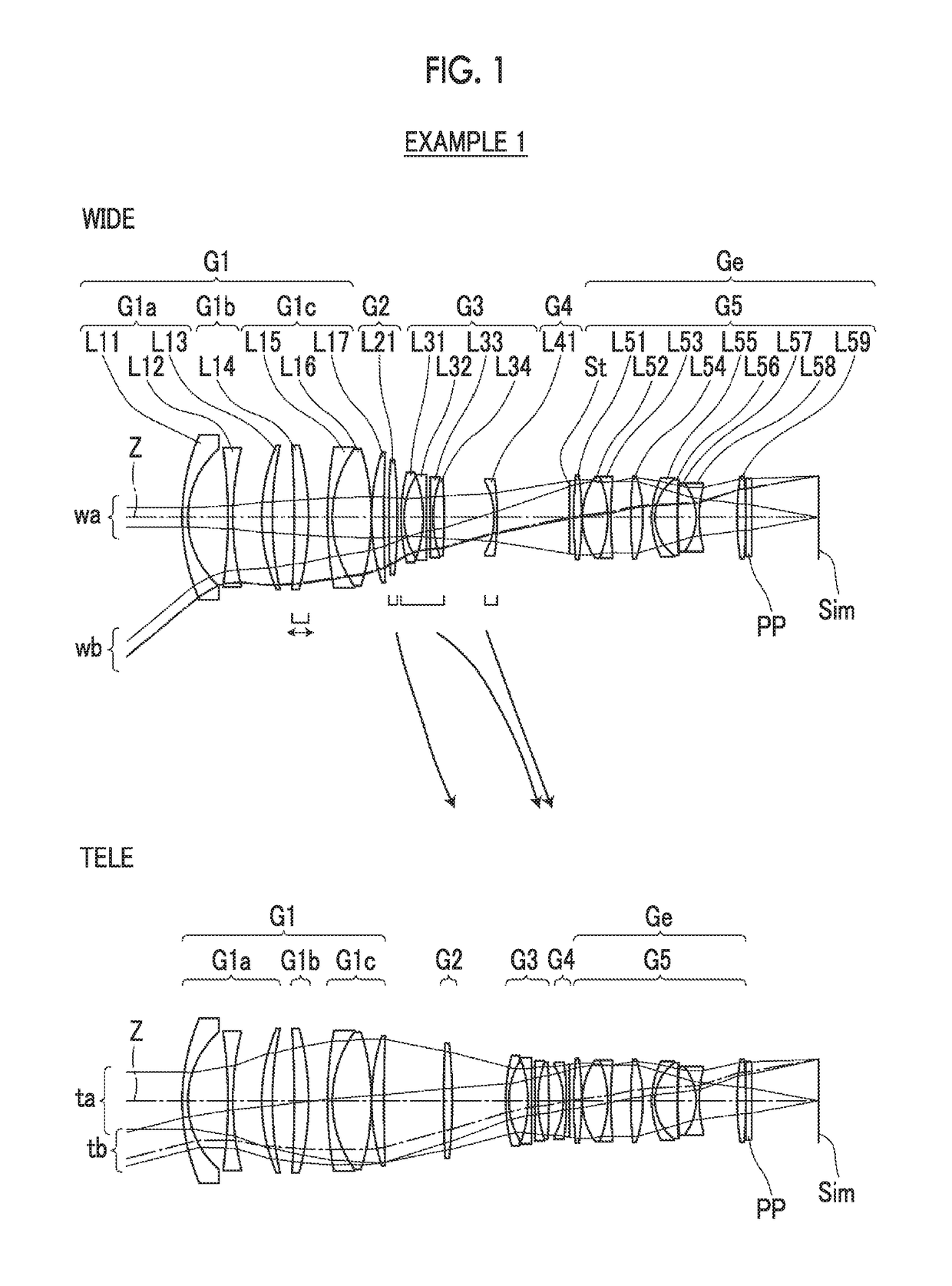
[0089]A lens configuration of a zoom lens of Example 1 is shown in FIG. 1, and an illustration method thereof is as described above. Therefore, repeated description is partially omitted herein. The zoom lens of Example 1 consists of, in order from the object side, a first lens group G1 having a positive refractive power, a second lens group G2 having a positive refractive power, a third lens group G3 having a negative refractive power, a fourth lens group G4 having a negative refractive power, and a fifth lens group G5 having a positive refractive power. In these five lens groups, the distances in the direction of the optical axis between groups adjacent to each other change during zooming. The movable lens groups are the second lens group G2, the third lens group G3, and the fourth lens group G4, and the final lens group Ge is the fifth lens group G5.

[0090]The first lens group G1 consists of, in order from the object side, a first lens group front group G1a having a negative refrac...

example 2

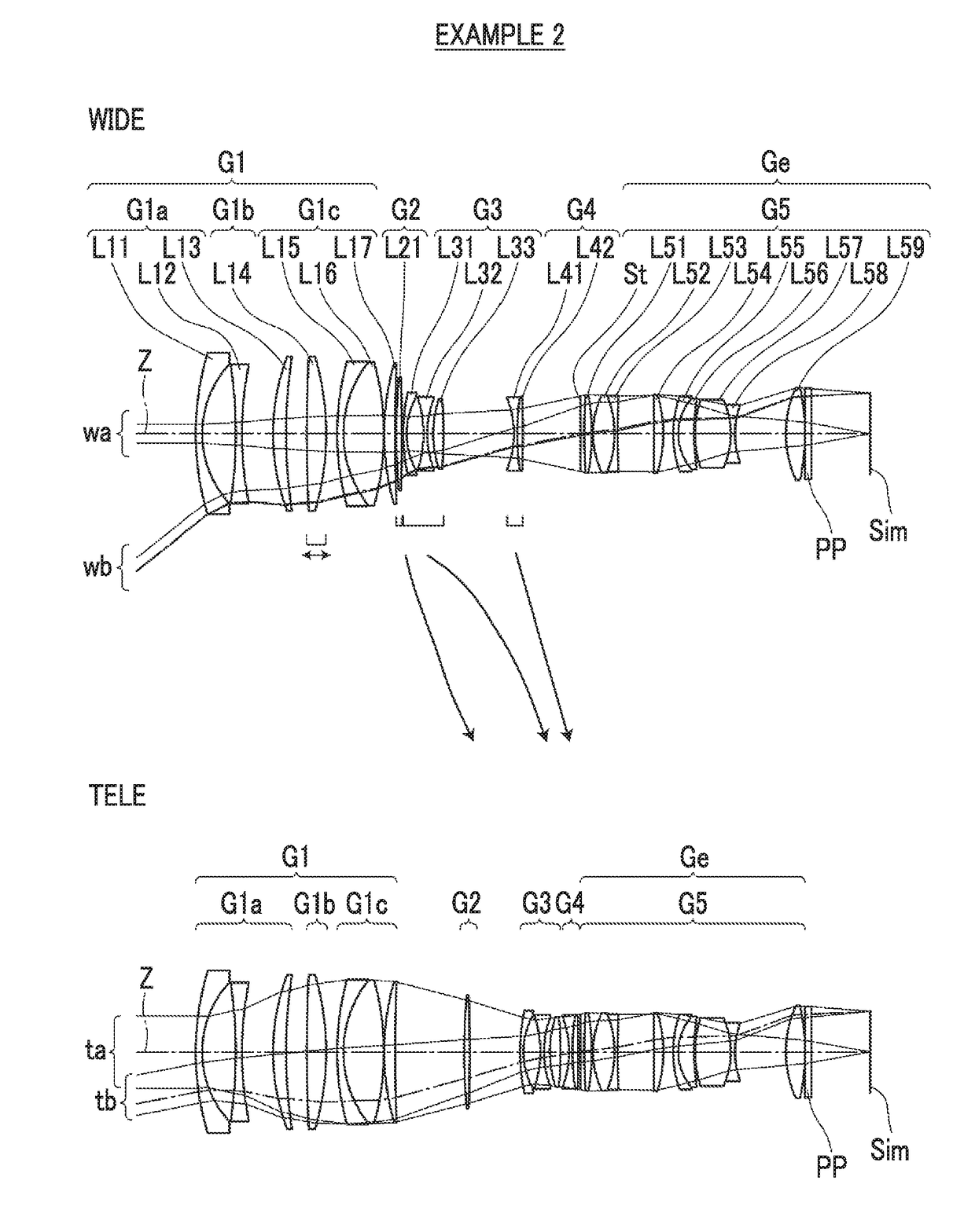
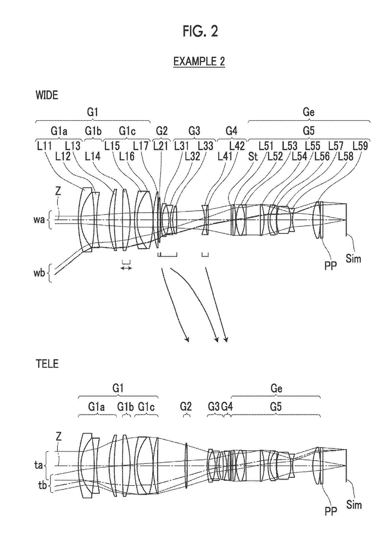
[0098]FIG. 2 shows a lens configuration and an optical path of a zoom lens of Example 2. The zoom lens of Example 2 is the same as that of Example 1 in terms of: the group configuration; the reference signs of the refractive powers of the respective lens groups; the lens groups that move during zooming; and the lens groups that move during focusing. The first lens group front group G1a consists of three lenses L11 to L13 in order from the object side, the first lens group intermediate group G1b consists of one lens L14, and the first lens group rear group G1c consists of three lenses L15 to L17 in order from the object side. The second lens group G2 consists of one lens L21. The third lens group G3 consists of three lenses L31 to L33 in order from the object side. The fourth lens group G4 consists of two lenses L41 and L42 in order from the object side. The fifth lens group G5 consists of an aperture stop St and nine lenses L51 to L59 in order from the object side.

[0099]Table 3 show...

example 3

[0100]FIG. 3 shows a lens configuration and an optical path of a zoom lens of Example 3, The zoom lens of Example 3 consists of, in order from the object side, a first lens group G1 having a positive refractive power, a second lens group G2 having a positive refractive power, a third lens group G3 having a negative refractive power, a fourth lens group G4 having a positive refractive power, and a fifth lens group G5 having a positive refractive power. The first lens group G1 consists of, in order from the object side, a first lens group front group G1a, a first lens group intermediate group G1b, and a first lens group rear group G1c. The zoom lens of Example 2 is the same as that of Example 1 in terms of the lens groups that move during zooming and the lens groups that move during focusing.

[0101]The first lens group front group G1a consists of three lenses L11 to L13 in order from the object side, the first lens group intermediate group G1b consists of one lens L14, and the first le...


PUM


Abstract

The zoom lens consists of, in order from the object side, a first lens group that has a positive refractive power and remains stationary during zooming, a plurality of movable lens groups that move during zooming, and a final lens group that has a positive refractive power and remains stationary during zooming. The first lens group consists of, in order from the object side, a first lens group front group that has a negative refractive power and remains stationary during focusing, a first lens group intermediate group that has a positive refractive power and moves during focusing, and a first lens group rear group that has a positive refractive power. The first lens group front group has, successively in order from a position closest to the object side, a negative meniscus lens that is concave toward the image side and a negative lens.

Description

CROSS-REFERENCE TO RELATED APPLICATIONS[0001]The present application claims priority under 35 U.S.C. § 119 to Japanese Patent Application No. 2017-000494, filed on Jan. 5, 2017. The above application is hereby expressly incorporated by reference, in its entirety, into the present application.BACKGROUND OF THE INVENTION1. Field of the Invention[0002]The present invention relates to a zoom lens suitable for electronic cameras such as movie imaging cameras, broadcast cameras, digital cameras, video cameras, and surveillance cameras, and to an imaging apparatus comprising the zoom lens.2. Description of the Related Art[0003]In the related art, a zoom lens having a four-group configuration or a five-group configuration is used as a lens system that can be used for cameras in the above-mentioned fields. For movie imaging cameras and broadcast cameras, the change in the total length of the lens system due to zooming and the change in the angle of view caused by focusing are undesirable. Th...

Claims


Application Information

Patent Timeline
Patent Type & Authority Applications(United States)
IPC IPC(8): G02B15/167G02B15/20
CPCG02B15/167G02B15/20G02B15/177G02B15/144109G02B15/145119G02B15/145127
Inventor YONEZAWA, MASARUTANAKA, TAKUYA
Owner FUJIFILM CORP
Why Eureka
Try Eureka