Tire demounting machine

Inactive Publication Date: 2018-07-12
FERRARI GINO +1
View PDF5 Cites 1 Cited by
  • Summary
  • Abstract
  • Description
  • Claims
  • Application Information

AI Technical Summary

Benefits of technology

[0032]reduced number of parts, which makes the tire demounting device much simpler and less expensive than prior

Problems solved by technology

This prior art suffers from certain drawbacks.
A first drawback is that four-bar linkage structures have a complex actuating structure, as they require the lengths of the connecting rods to be accurately sized and the hinge points between parts to be positioned with the same accuracy, for the hook member to follow its proper roto-translational path.
A second drawback is that, with time, the stresses exerted on the hook member and the four-bar linkage structure, both for fitting between the tire and the rim and for removing the

Method used


Image

  • Tire demounting machine
  • Tire demounting machine
  • Tire demounting machine

Examples


Example

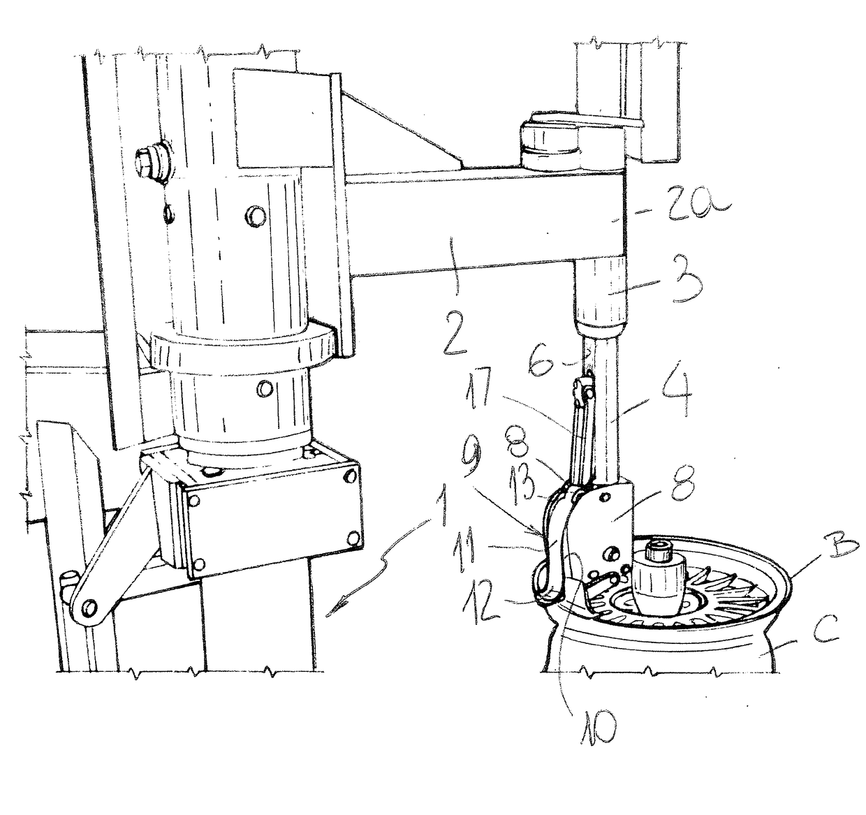
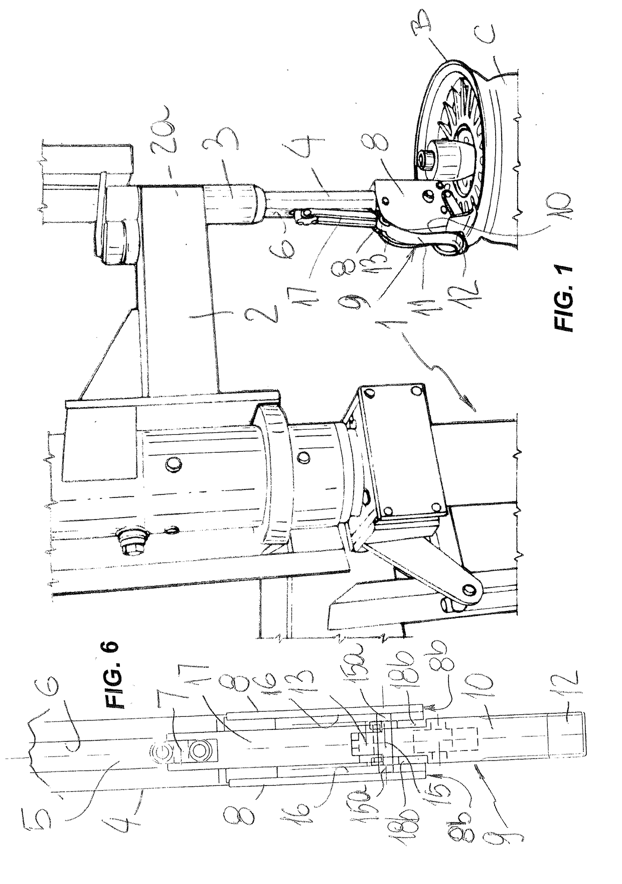
[0039]Referring to the above mentioned figures, numeral 1 designates a vertical column of a conventional tire changing machine.

[0040]Numeral 2 designates a horizontal arm which is rotatingly articulated to the column 1 as is known by the skilled person.

[0041]The arm 2 has a free end 2a facing away from the column 1 and outwards, having a vertical sleeve 3 associated therewith, for a work tool-carrying rod 4 to coaxially and controllably slide therein.

[0042]A pneumatic cylinder (not shown) is associated with the rod 4, and has its shaft 5 mounted to slide relative to the rod 4, e.g. within the rod 4.

[0043]The latter has a longitudinal slot 6 in which a block 7 is slidingly guided, which block is rigidly joined to the shaft 5, so that it can be moved therewith.

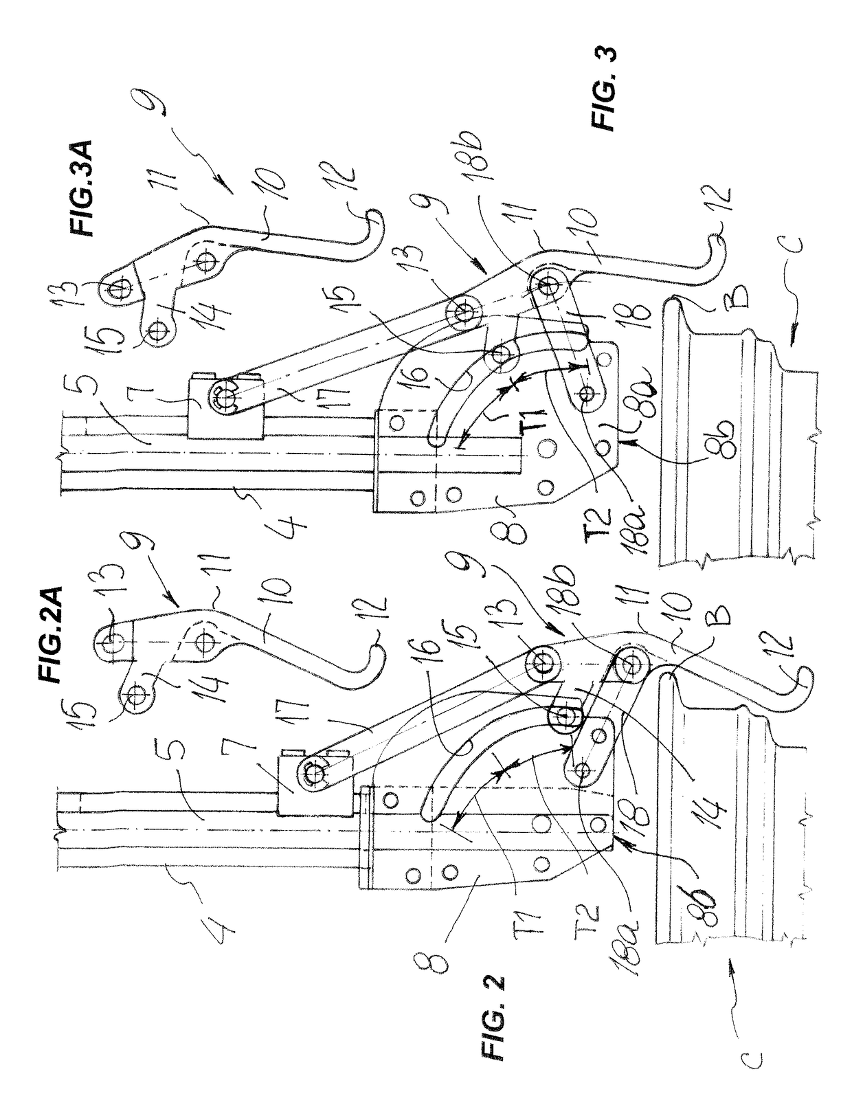
[0044]Two parallel plates 8, here extending vertically, are attached to the lower end of the rod 4, and have a gap therebetween for a hook member 9 to be received therein, and move along a roto-translational path between an inse...


PUM


Abstract

A tire demounting device includes a hook member having an elongate body that forms a hook at an end to be disposed lowerly and has a connection point at an opposite end, a pair of parallel plates having the hook member roto-translationally movable therebetween, a connection system that connects the plates to a support element, a drive system that moves the body between an inserted position to fit between a tire and the edge of a rim, and a removal position to remove the tire from the rim, the drive system being connected to the connection point, a connecting rod having one end hinged to the body and an opposite end hinged to the plates, so as to rotate parallel thereto along a circular arc path, the body having a pin, which is supported transverse and perpendicular to the plates, which have a specially shaped guide track for the pin.

Description

FIELD OF THE INVENTION[0001]The invention relates to a tire demounting device, which is generally designed to lift the bead of a tire and remove it from the tire fitting groove of a rim upon which it is mounted, without hitting the edge of the rim.BACKGROUND ART[0002]Tire demounting devices have been long known to be used on tire changing machines to assist removal of tires from the rims upon which they are mounted.[0003]These tire demounting devices are mounted at the lower end of a vertical rod, generally known as “pole”, which is mounted at the free end of a horizontal arm that extends from the top of a column that raises from the base of a tire changing machine, to alternately pivot on a substantially horizontal plane perpendicular to the column.[0004]These devices comprise a removing hook member, which is supported and moved between two operating positions by a specially designed support unit which connects it to the pole.[0005]The two operating positions are namely a rest posi...

Claims


Application Information

Patent Timeline
IPC IPC(8): B60C25/138B60C25/05
CPCB60C25/138B60C25/0578
Inventor FERRARI, GINOMAIOLI, FRANCO
Owner FERRARI GINO
Why Eureka
Try Eureka