Automated footwear platform having upper elastic tensioner

a technology of elastic tensioner and footwear platform, which is applied in the direction of lacing hooks, fastenings, uppers, etc., can solve the problems of reducing the ability of the wearer of the footwear to tighten the upper around the foot, affecting and reducing the comfort of the wearer. , to achieve the effect of facilitating access to the interior spa

Active Publication Date: 2018-07-19
NIKE INC
View PDF11 Cites 16 Cited by
  • Summary
  • Abstract
  • Description
  • Claims
  • Application Information

AI Technical Summary

Benefits of technology

[0009]A footwear assembly comprises: a sole structure; a footwear upper defining a toe box portion, a medial side, a lateral side, and a heel portion, the footwear upper connected to the sole structure to form an interior space for receiving a foot, the footwear upper forming a collar to permit access to the interior space; a lacing engine disposed in the sole structure; a lacing system c

Problems solved by technology

Current footwear uppers generally have fixed dimensions and therefore do not readily permit either to conform to the shape of the foot.
However, in footwear including motorized lacing engines, the ability

Method used


Image

  • Automated footwear platform having upper elastic tensioner
  • Automated footwear platform having upper elastic tensioner
  • Automated footwear platform having upper elastic tensioner

Examples


example 1

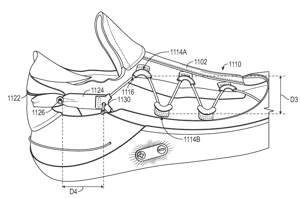
[0120 can include or use subject matter such as a footwear assembly comprising: a footwear upper including a toe box portion, a medial side, a lateral side, and a heel portion, the medial side and the lateral side each extending proximally from the toe box portion to the heel portion; a lace cable with a first end anchored along a distal outside portion of the medial side and a second end anchored along a distal outside portion of the lateral side; a plurality of lace guides distributed along the medial side and the lateral side, each lace guide of the plurality of lace guides adapted to receive a length of the lace cable, wherein the lace cable extends through each of the plurality of lace guides to form a pattern along each of the medial side and lateral side of the footwear upper; a medial proximal lace guide routing the lace cable from the pattern formed by a medial portion of the plurality of lace guides into a position allowing the lace cable to engage a lacing engine disposed...

example 7

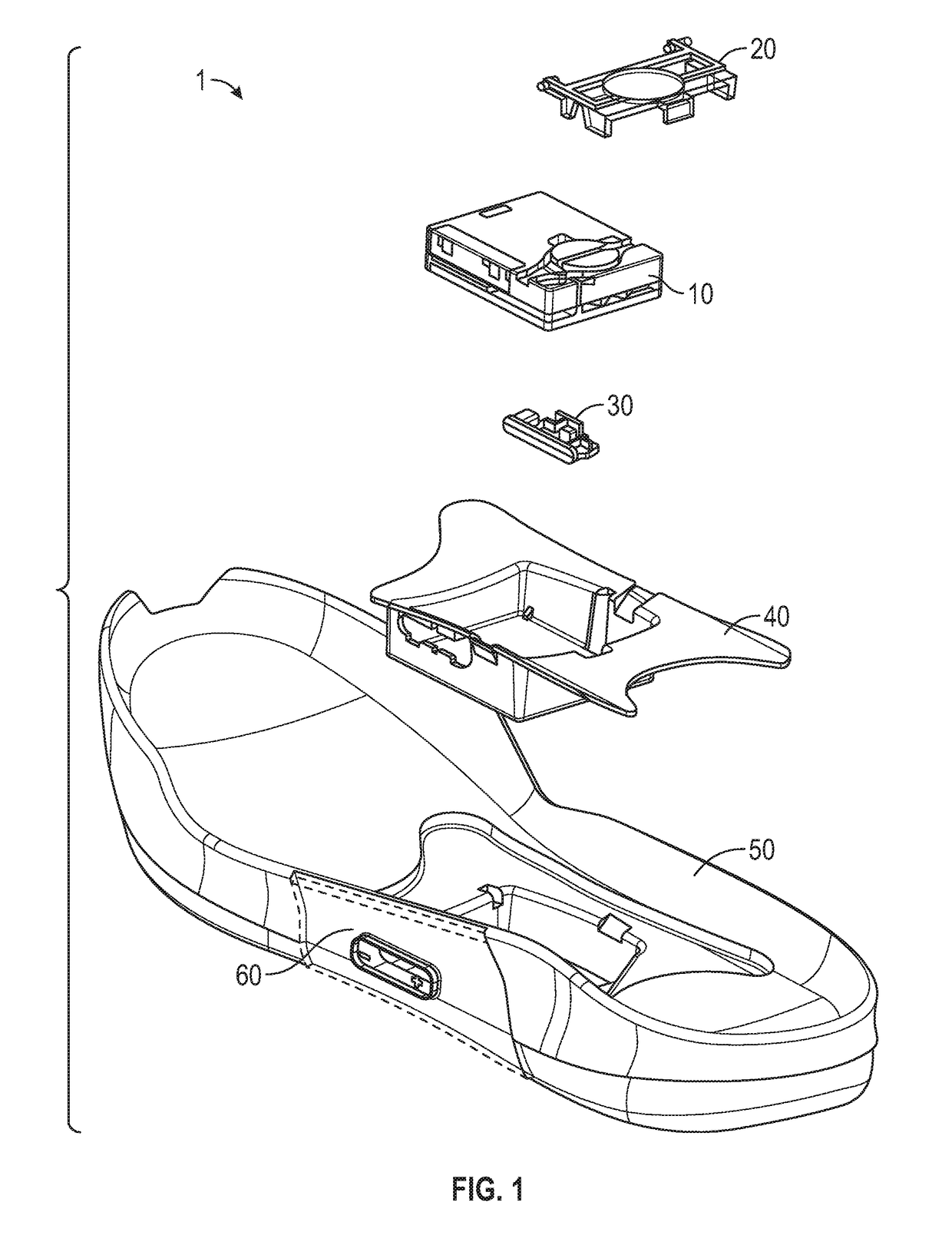
[0126 can include or use subject matter such as a footwear lacing apparatus that can comprise: a housing structure that can comprise: a footwear assembly comprising: a footwear upper including a toe box portion, a medial side, a lateral side, and a heel portion, the medial side and the lateral side each extending proximally from the toe box portion to the heel portion; a lace cable with a first end anchored along a distal outside portion of the medial side and a second end anchored along a distal outside portion of the lateral side; a plurality of lace guides distributed along the medial side and the lateral side, each lace guide of the plurality of lace guides adapted to receive a length of the lace cable, wherein the lace cable extends through each of the plurality of lace guides to form a pattern along each of the medial side and lateral side of the footwear upper; a medial proximal lace guide routing the lace cable from the pattern formed by a medial portion of the plurality of ...

example 12

[0131 can include or use subject matter such as a footwear lacing apparatus that can comprise: a footwear assembly comprising: a footwear upper including a toe box portion, a medial side, a lateral side, and a heel portion, the medial side and the lateral side each extending proximally from the toe box portion to the heel portion; a lace cable with a first end anchored along a distal outside portion of the medial side and a second end anchored along a distal outside portion of the lateral side; a plurality of lace guides distributed along the medial side and the lateral side, each lace guide of the plurality of lace guides adapted to receive a length of the lace cable, wherein the lace cable extends through each of the plurality of lace guides to form a pattern along each of the medial side and lateral side of the footwear upper; a medial proximal lace guide routing the lace cable from the pattern formed by a medial portion of the plurality of lace guides into a position allowing th...


PUM


Abstract

A footwear assembly can comprise, an upper, a lace cable, a plurality of lace guides and a tensioner. The tensioner can comprise an elastic member extending between two lace guides of the plurality of lace guides, an elastic member extending between first and second portions of the upper, an elastic member extending between a portion of the upper and a lace guide of the plurality of lace guides, a heel channel connected to a heel portion of the upper and configured to facilitate access to an interior space, an elastic member coupled to the footwear assembly that functions to smooth out a torque versus lace displacement curve during tightening of the lace cable.

Description

CLAIM OF PRIORITY[0001]This application claims the benefit of priority to U.S. Provisional Patent Application Ser. No. 62 / 471,850, filed on Mar. 15, 2017; and U.S. Provisional Patent Application Ser. No. 62 / 475,105, filed on Mar. 22, 2017, which are hereby incorporated by reference herein in their entirety.[0002]This patent application is also a continuation-in-part of and claims priority to U.S. patent application Ser. No. 15 / 458,824, filed on Mar. 14, 2017, which claims the benefit of priority to U.S. Provisional Patent Application Ser. No. 62 / 424,301, filed on Nov. 18, 2016, and U.S. Provisional Patent Application Ser. No. 62 / 413,142, filed on Oct. 26, 2016, which are incorporated by reference in their entirety.BACKGROUND[0003]The present application relates generally to tensioning systems for footwear. More particularly, the present application relates to uppers and lacing systems for controlling footwear fit.[0004]Current footwear uppers generally have fixed dimensions and ther...

Claims


Application Information

Patent Timeline
IPC IPC(8): A43C11/16A43B23/02A43B13/14A43C1/00A43C7/06A43B3/00
CPCA43C11/165A43B23/0245A43B13/14A43C1/00A43C7/06A43B3/0005A43B11/00A43C3/00A43C11/008A43B3/34
Inventor SCHNEIDER, SUMMER L.CHANG, NARISSAAVAR, ERIC P.BELL, THOMAS G.ANDON, CHRISTOPHER
Owner NIKE INC
Why Eureka
Try Eureka