Supercharge Your Innovation With Domain-Expert AI Agents!

Z-notch shape for a turbine blade tip shroud

a turbine blade and tip shroud technology, applied in the field of turbine blades, can solve the problems of shortening the useful life of the tip shroud, and the tip shroud becomes highly stressed

Active Publication Date: 2018-07-19
GENERAL ELECTRIC CO
View PDF0 Cites 5 Cited by
  • Summary
  • Abstract
  • Description
  • Claims
  • Application Information

AI Technical Summary

Benefits of technology

This patent describes a turbine blade with a tip shroud that has a specific profile shape. The purpose of this profile shape is to improve the performance and efficiency of the turbine blade. The tip shroud edge has a specific shape that fits within a certain range of values in a Cartesian coordinate system. This shape is achieved through a process of scaling and connecting certain distances in the coordinate system. The technical effect of this patent is to provide a specific profile shape for the tip shroud edge that enhances the performance and efficiency of the turbine blade.

Problems solved by technology

During operation, tip shrouds become highly stressed because of the mechanical forces applied to them via the rotational velocity of the turbine.
The high temperature environment of the turbine coupled with the high stress level quickens the rate at which these parts deform or degrade, which shortens their useful life.
When designing tip shrouds, finding the proper balance between these competing objectives—i.e., extended useful part life and efficient engine performance—is a challenge.

Method used


Image

  • Z-notch shape for a turbine blade tip shroud
  • Z-notch shape for a turbine blade tip shroud
  • Z-notch shape for a turbine blade tip shroud

Examples


Embodiment Construction

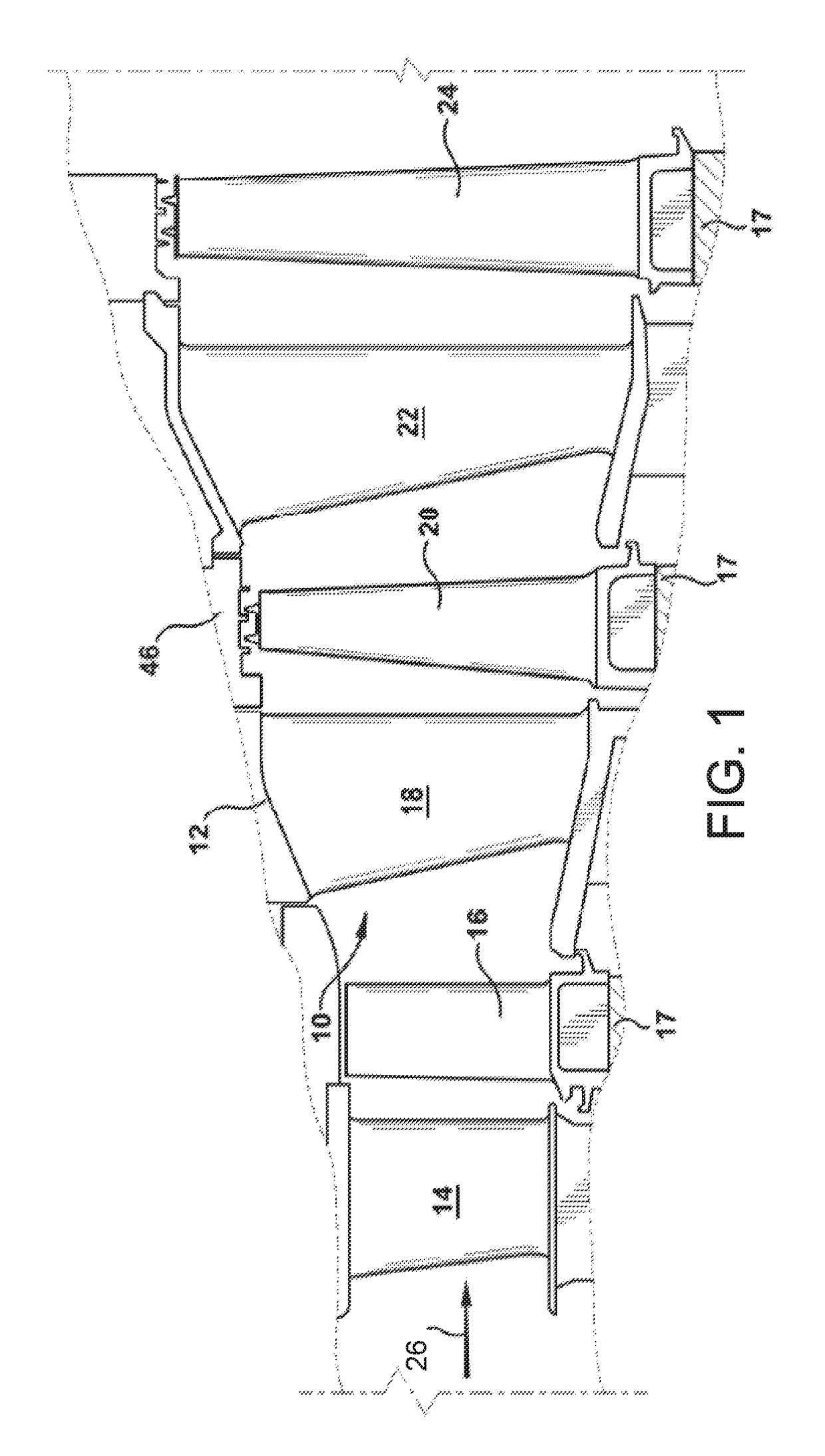
[0013]Referring now to the figures, FIG. 1 illustrates a hot gas path, generally designated 10, of a gas turbine 12 that includes a plurality of turbine stages. Three stages are illustrated. A first stage may include a plurality of circumferentially spaced nozzles 14 and turbine blades (or buckets) 16. The first stage nozzles 14 generally are circumferentially spaced one from the other and fixed about the axis of the rotor (not shown). The first stage blades 16 may be mounted on a turbine wheel 17 for rotation about the rotor when hot gases are expanded through the hot gas path 10. A second stage of the turbine 12 is also illustrated. The second stage similarly may include a plurality of circumferentially spaced nozzles 18 and a plurality of circumferentially spaced blades 20 mounted on a turbine wheel 17. A third stage also is illustrated and includes a plurality of circumferentially spaced nozzles 22 and blades 24 mounted on a turbine wheel 17. It will be appreciated that the nozz...


PUM


Abstract

A turbine blade includes an airfoil having a tip shroud. The tip shroud has an edge, and the edge has a profile substantially in accordance with values of X and Y in a Cartesian coordinate system set forth in Table 1 at points 1-30. The X and Y values represent distances that may be proportionally scaled by a common multiplier which, once scaled and connected, define the profile of the edge of the tip shroud. The profile of the edge lies in an envelope within + / −20%, + / −10% or + / −0% in a direction normal to any location along the edge set forth by the points in Table 1.

Description

BACKGROUND OF THE INVENTION[0001]The present invention relates to turbine blades having an airfoil and a tip shroud carried by the airfoil. More specifically, the present invention relates to z-notch edge profiles for a tip shroud.[0002]Turbine blades (or buckets) typically comprise an airfoil, a platform, a shank and a dovetail. In operation, the dovetail is secured in a complementary slot in a turbine wheel. On many airfoils, integral tip shrouds are used on the outer radial end of the airfoil to create an outer surface of the passage through which the hot gasses must pass. Having the tip shroud as a part of the airfoil increases the efficiency of the turbine engine. Moreover, in general, larger tip shrouds enhance turbine performance more than smaller ones. As such, in one respect, it is desirable to have the entire outer radial surface of the airfoil covered by a relatively large tip shroud.[0003]During operation, tip shrouds become highly stressed because of the mechanical forc...

Claims


Application Information

Patent Timeline
Patent Type & Authority Applications(United States)
IPC IPC(8): F01D5/22F01D5/20
CPCF01D5/225F01D5/20F05D2240/307F05D2230/80F05D2220/32F05D2250/74F05D2250/75F05D2240/306Y02T50/60
Inventor ZEMITIS, WILLIAM SCOTTRODRIGUEZ, ANTONIONEVILLE, JASON ADAM
Owner GENERAL ELECTRIC CO
Features
  • R&D
  • Intellectual Property
  • Life Sciences
  • Materials
  • Tech Scout
  • Unparalleled Data Quality
  • Higher Quality Content
  • 60% Fewer Hallucinations
Learn More