
Floor cleaner, and cleaning mechanism for clearing cleaning roller

a cleaning mechanism and cleaning roller technology, applied in vacuum cleaners, carpet cleaners, domestic applications, etc., can solve the problems of reducing the clearing effect of the vacuum cleaner, stains are firmly attached to the ground, and the vacuum cleaner cannot eliminate the waste, so as to achieve stable and reliable connection mode, the effect of maintaining good cleaning

Active Publication Date: 2018-07-26
HIZERO APPLIANCES CORP
View PDF2 Cites 8 Cited by
  • Summary
  • Abstract
  • Description
  • Claims
  • Application Information

AI Technical Summary

Benefits of technology

The cleaning mechanism described in this patent includes a cleaning roller, a clearing component, and a power unit. The clearing component is designed to clear the roller by using a rotating body and multiple clearing elements. The power unit drives the roller, clearing elements, and the entire cleaning mechanism to rotate in the same direction to remove trash from the roller. Compared to traditional baffle plates, the connection between the clearing elements and the rotation body is stable and reliable, ensuring the cleaner's ability to maintain its effectiveness even after extended use.

Problems solved by technology

However, due to the limitation of the working principle, the vacuum cleaner fails to eliminate the waste and stains firmly attached to the ground.
However, because the baffle plate is fixed on the dust bin, after long term of use, it tends to deform, thus greatly decreasing the clearing effect of the cleaner.

Method used


Image

  • Floor cleaner, and cleaning mechanism for clearing cleaning roller
  • Floor cleaner, and cleaning mechanism for clearing cleaning roller
  • Floor cleaner, and cleaning mechanism for clearing cleaning roller

Examples


example 1

[0043]To better clear conventional cleaning roller, a novel cleaning mechanism for clearing a cleaning roller of a cleaner is provided.

[0044]The cleaning mechanism comprises: a cleaning roller for cleaning ground, a clearing component operating to clearing the cleaning roller, and a power unit

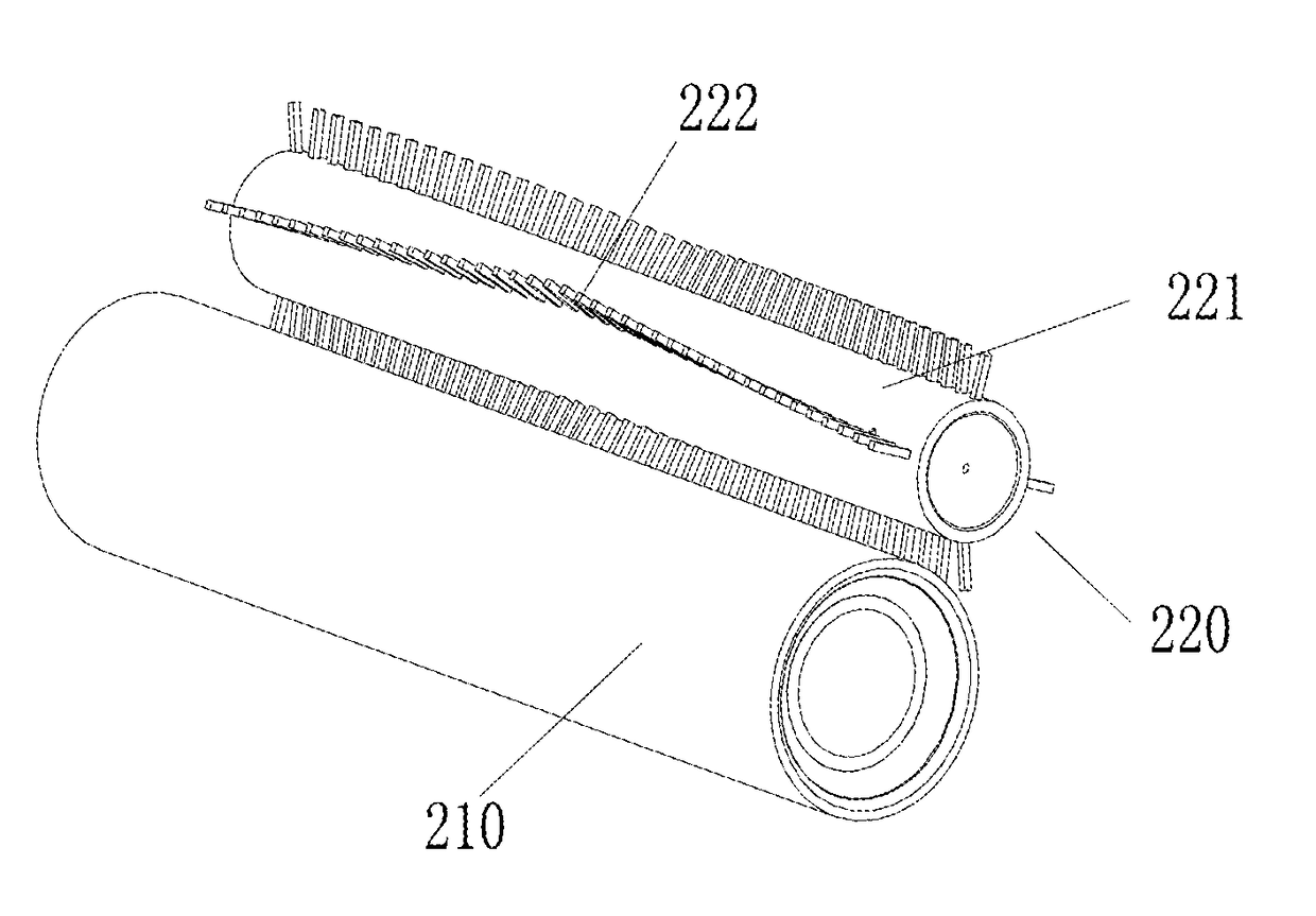
[0045]The clearing component comprises a rotation body and a plurality of clearing elements disposed on the rotation body for clearing a surface of the cleaning roller. The rotation body is a hollow tube or a solid shaft. The clearing component is fixed on the rotation body and protrudes therefrom. The power unit operates to drive the rotation body and the clearing elements to rotate along with the cleaning roller in a same direction.

[0046]Preferably, the clearing elements are strip-shaped, and one end of each strip-shaped clearing element is fixed on the rotation body, the other end thereof stretches to the cleaning roller.

[0047]One end of each clearing element stretching to the cleaning rolle...

example 2

[0051]The disclosure provides a cleaner for cleaning the ground.

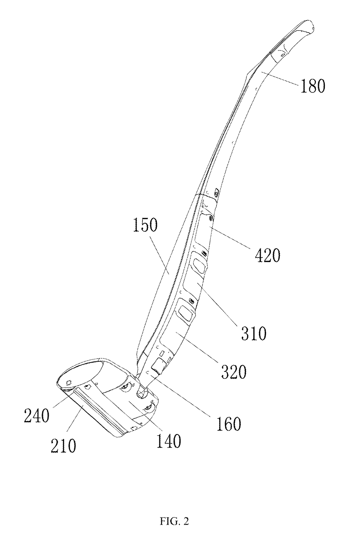
[0052]The cleaner for cleaning the ground comprises a shell assembly, a cleaning mechanism, a water supply system, a control unit, and a connection mechanism.

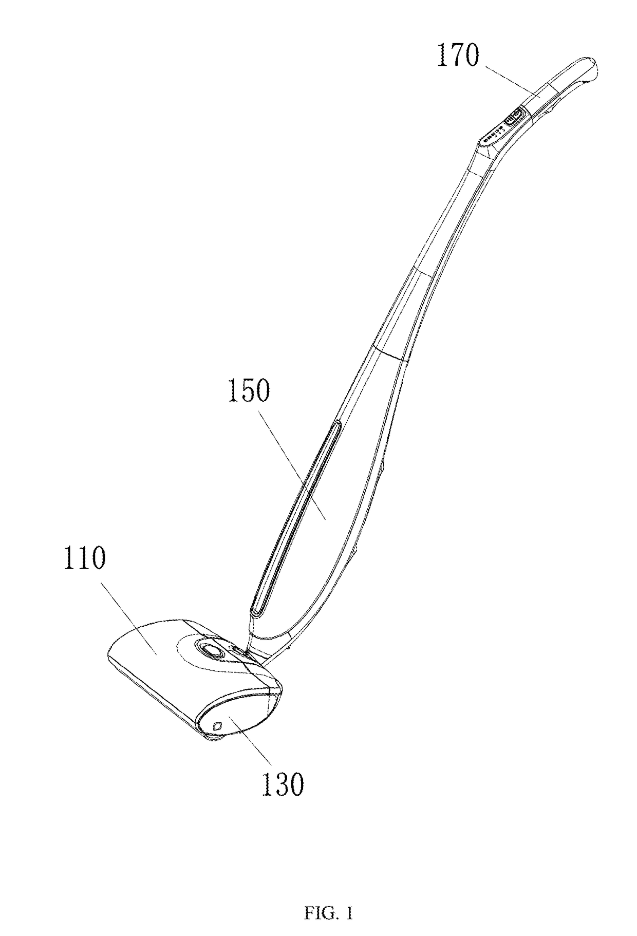
[0053]The shell assembly is a support of the cleaner, and comprises two parts, one is a base, the other is a handle. The base and the handle is connected by the connection mechanism. The connection mode is flexible, so that the user can conveniently operate the cleaner with different angles.

[0054]The cleaning mechanism is a key part to clean the ground and is disposed on the base. The water supply system comprises a clean water tank and a wastewater tank. The clean water tank is configured to store clean water and communicates with the cleaning mechanism. Clean water is transported to the cleaning mechanism through a power unit to clean the cleaning mechanism. The wastewater tank is configured to store wastewater which is discharged from the cleaning mechanism comm...


PUM


Abstract

A cleaning mechanism for clearing a cleaning roller of a cleaner. The cleaning mechanism includes: a cleaning roller for cleaning ground, a clearing component operating to clearing the cleaning roller, and a power unit. The clearing component includes a rotation body and a plurality of clearing elements disposed on the rotation body for clearing a surface of the cleaning roller. The power unit operates to drive the rotation body and the clearing elements to rotate along with the cleaning roller in the same direction. During the rotation of the cleaning roller, the trash is cleared by the clearing elements.

Description

FIELD OF THE DISCLOSURE[0001]The disclosure relates to cleaning equipment, and more particularly to a cleaning mechanism for clearing a cleaning roller of a cleaner.BACKGROUND OF THE DISCLOSURE[0002]Conventional cleaners for cleaning ground include brooms, mops and floor wipers, all of which are manual tools. With the development of science and technology, people pose high requirements for cleaners, and vacuum cleaner is developed, which operates to adsorb waste and dust on the ground through negative pressure produced by electric power. However, due to the limitation of the working principle, the vacuum cleaner fails to eliminate the waste and stains firmly attached to the ground. As a result, a new generation of cleaners for cleaning ground is provided. The new generation of cleaners includes a motor and a cleaning roller which is driven by the motor to clean the ground. The new generation of cleaners is equipped with a water supply system for washing the cleaning roller, thus cap...

Claims


Application Information

Patent Timeline
Patent Type & Authority Applications(United States)
IPC IPC(8): A47L9/04A47L11/40
CPCA47L9/0477A47L11/4041A47L11/4013A47L11/282A47L11/4044
Inventor LI, YANGZHANG, YONG
Owner HIZERO APPLIANCES CORP
Learn More