Reflective illumination systems for optically widened perception

a technology of optical widened perception and reflection illumination, applied in the field of lighting systems, can solve problems such as affecting perception

Active Publication Date: 2018-07-26
COELUX
View PDF0 Cites 6 Cited by
  • Summary
  • Abstract
  • Description
  • Claims
  • Application Information

AI Technical Summary

Benefits of technology

[0032]The chromatic effect is further based on nanoparticles having a refractive index that is different than the refractive index of the embedding matrix. To scatter, the nanoparticles have a real refractive index np sufficiently different from that of the matrix nh, (also referred to as host material) in order to allow light scattering to take place. For example, the ratio m between the particle and host medium refractive indexes
[0033]The chromatic effect is further based on the number of nanoparticles per unit area seen by the impinging light propagating in the given direction as well as the volume-filling-fraction f. The volume filling fraction f is given by
[0034]The chromatic effect is further based on a number N of nanoparticles per unit area of the chromatic diffusive layer in dependence of an effective particle diameter D=d nh. Thereby, d [meter] is the average particle size defined as the average particle diameter in the case of spherical particles, and as the average diameter of volume-to-area equivalent spherical particles in the case of non-spherical particles, as defined in [T. C. GRENFELL, AND S. G. WARREN, “Representation of a non-spherical ice particle by a collection of independent spheres for scattering and absorption of radiation”. Journal of Geophysical Research 104, D24, 31,697-31,709. (1999)]. The effective particle diameter is given in meters or, where specified in nm.

Problems solved by technology

[6] Introducing a reflective feature as, for example, in PCT / EP2014 / 059802 mentioned above, however, may affect the perception due to the presence of the reflection.

Method used


Image

  • Reflective illumination systems for optically widened perception
  • Reflective illumination systems for optically widened perception
  • Reflective illumination systems for optically widened perception

Examples


Embodiment Construction

[0078]The following is a detailed description of exemplary embodiments of the present disclosure. The exemplary embodiments described therein and illustrated in the drawings are intended to teach the principles of the present disclosure, enabling those of ordinary skill in the art to implement and use the present disclosure in many different environments and for many different applications. Therefore, the exemplary embodiments are not intended to be, and should not be considered as, a limiting description of the scope of patent protection. Rather, the scope of patent protection shall be defined by the appended claims.

[0079]The disclosure is based in part on the realization that in illumination systems like those described in the above mentioned PCT / EP2014 / 059802 the specular reflection of a surrounding scene, as for example a scene of a recognizable indoor or outdoor environment or any scene featuring a spatially structured luminance distribution, is superimposed as a background to ...


PUM


Abstract

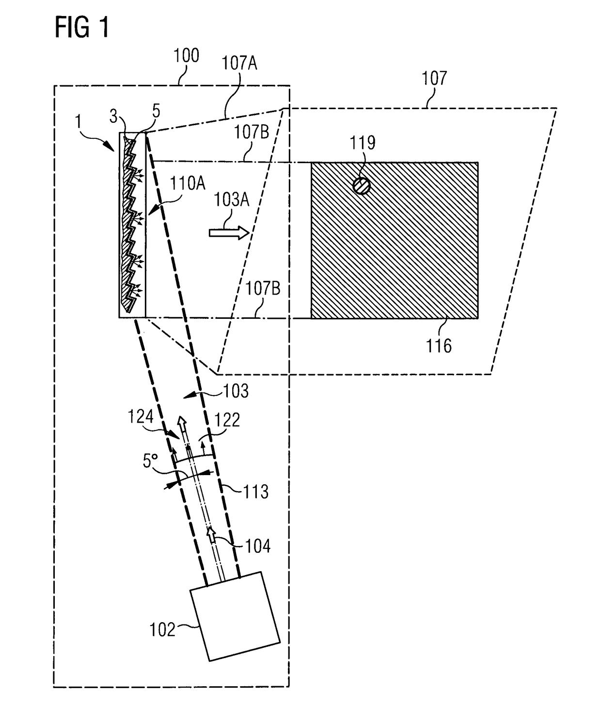
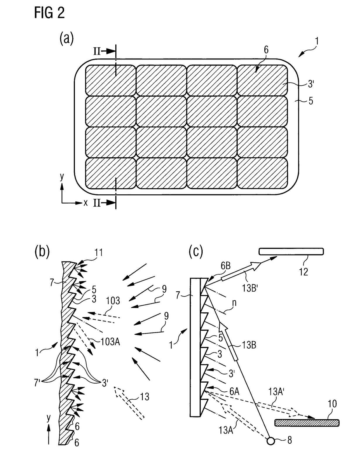
In an aspect, an illumination system (100) is disclosed to comprise a light source (102) configured to generate a light beam (103), and a chromatic reflective unit (1) for being illuminated by the light beam (103). The chromatic reflective unit (1) comprises a plurality of non-coplanar reflective surface sections (3′), and a chromatic diffusing layer (5) comprises a plurality of nanoparticles (37) embedded in a matrix (39), wherein the chromatic diffusing layer (5) is provided upstream of the plurality of reflective surface sections (3′) such that at least a portion of the light beam (103) passes through the chromatic diffusing layer (5) before and after being reflected by the plurality of non-coplanar reflective surface sections (3′). Chromatic diffusing layer (5) is further configured to provide for—together with non-coplanar reflective surface sections (3′)—a specular reflectance that is larger in the red than in the blue and for a diffuse reflectance that is larger in the blue than in the red.

Description

TECHNICAL FIELD[0001]The present disclosure relates generally to lighting systems, in particular to lighting systems for optically providing a widened perception / impression of the ambient space and in particular for imitating natural sunlight illumination. Moreover, the present disclosure relates generally to implementing such a lighting system, for example, in an indoor room or an outdoor environment.BACKGROUND[0002]The improvements in mirror manufacturing techniques during the 16th century caused an increasing use of optical mirror elements in interior architecture. For example, the overlay of a portion of a wall with a reflective surface generated the impression of space enhancement and an increase of depth perception. Since then, mirrors became essential components capable of improving the comfort of an ambience through a widening in the perceived volume. In general, in modern and contemporary architecture, reflective surfaces are used to provide for specific perceptions by an o...

Claims


Application Information

Patent Timeline
Patent Type & Authority Applications(United States)
IPC IPC(8): G02B5/02
CPCG02B5/0284G02B5/0215G02B5/0226G02B5/0294G02B5/0221G02B5/0242F21V7/0008
Inventor DI TRAPANI, PAOLOMAGATTI, DAVIDE
Owner COELUX
Why Eureka
Try Eureka