A neutron generator for neutron capture therapy
A kind of neutron generator and neutron technology, applied in the direction of nuclear reaction target, DC voltage accelerator, accelerator, etc., can solve the problems of small output, large volume and complex structure of neutron generator, and achieve the goal of working Long life, high power capacity, and the effect of increasing the probability of collision
- Summary
- Abstract
- Description
- Claims
- Application Information
AI Technical Summary
Problems solved by technology
Method used
Image
Examples
Embodiment 1
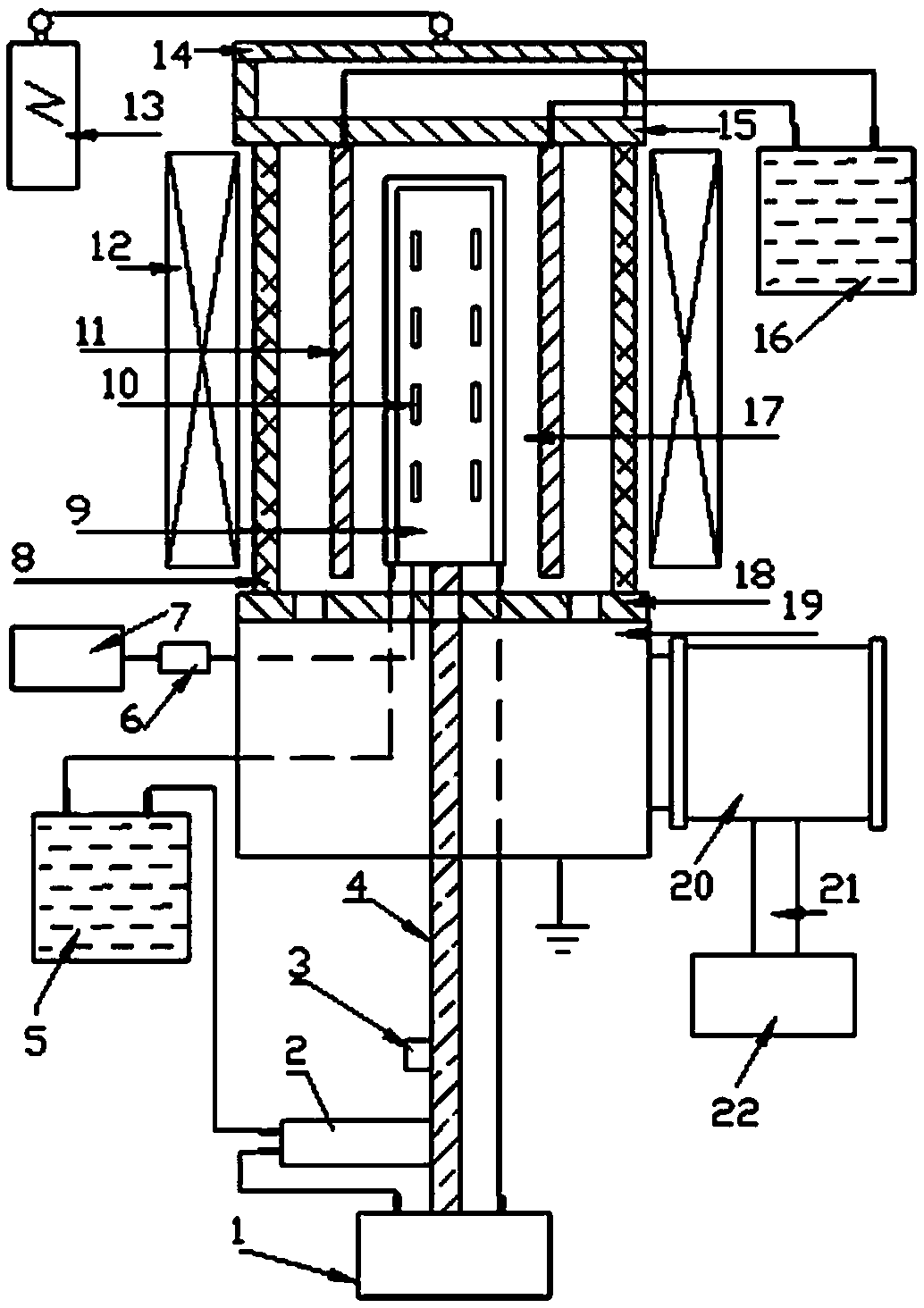
[0042] A neutron generator used in neutron capture therapy, such as figure 1 As shown, it includes a vacuum chamber, a vacuum pumping system disposed on the vacuum chamber, a target system disposed in the vacuum chamber, and an ion source system that guides ions to the target system.
[0043] Wherein, the ion source system includes a discharge chamber 9 arranged in the vacuum chamber, and an extraction electrode 10 arranged on the discharge chamber 9; the number of the extraction electrodes 10 is multiple, and is evenly distributed on the side wall of the discharge chamber 9, That is, the extraction electrodes 10 are evenly distributed on the side wall of the discharge chamber 9 at 360 degrees, such as figure 1 As shown; the target system includes a target 11 located in the vacuum chamber and arranged around the discharge chamber 9, and a negative high voltage power supply 13 connected to the target 11.
[0044] Step 1. Carry out vacuuming operation through the vacuuming syst...
Embodiment 2
[0047] The difference between this embodiment and Embodiment 1 is that this embodiment optimizes the structure of the target system and the ion source system, and the specific settings are as follows:
[0048] The ion source system also includes a microwave generator 1, one end is connected to the microwave generator 1, and the other end extends to a waveguide 4 in the discharge chamber 9, a microwave tuner 3 arranged on the waveguide 4, and a circulator connected to the waveguide 4 2. The deuterium cylinder 7 communicated with the discharge chamber 9 through the connecting pipe, the ceramic insulator 8 arranged on the vacuum chamber or outside the vacuum chamber, and the permanent magnet arranged outside the vacuum chamber and used to generate a magnetic field acting on the discharge chamber 9 12.
[0049] In this embodiment, both the target 11 and the ceramic insulator 8 are arranged in a cylindrical structure, the target 11 is located inside the ceramic insulator 8 of the c...
Embodiment 3
[0061] The difference between this embodiment and Embodiment 2 is that a low potential circulating water device 5 and a high potential circulating water device 16 are added in this embodiment, such as figure 1 As shown, the specific settings are as follows:
[0062] The ion source system is also provided with a low-potential circulating water device 5, the water outlet of the low-potential circulating water device 5 is connected to the water inlet of the discharge chamber 9 through a water pipe, and the water outlet of the discharge chamber 9 is connected to the microwave generator 1 through a water pipe. The water inlet is connected, the water outlet of the microwave generator 1 is connected with the water inlet of the circulator 2 through the water pipe, and the water outlet of the circulator 2 is connected with the water inlet of the low potential circulating water device 5 through the water pipe.
[0063] The target system also includes a high-potential circulating water d...
PUM
 Abstract
Description
Claims
Application Information
 - R&D
- Intellectual Property
- Life Sciences
- Materials
- Tech Scout
- Unparalleled Data Quality
- Higher Quality Content
- 60% Fewer Hallucinations
Browse by: Latest US Patents, China's latest patents, Technical Efficacy Thesaurus, Application Domain, Technology Topic, Popular Technical Reports.
© 2025 PatSnap. All rights reserved.Legal|Privacy policy|Modern Slavery Act Transparency Statement|Sitemap|About US| Contact US: help@patsnap.com

