
Antenna structure and wireless communication device with the antenna structure

An antenna structure and array antenna technology, applied in the connection of antenna grounding switch structure, components of resonant antenna, antenna, etc., can solve the problems of large dielectric loss, difficulty in realization, and short working wavelength of millimeter wave microstrip antenna

Active Publication Date: 2021-05-25
MOBILE DRIVE NETHERLANDS BV
View PDF7 Cites 0 Cited by
  • Summary
  • Abstract
  • Description
  • Claims
  • Application Information

AI Technical Summary

Problems solved by technology

[0002] In millimeter-wave products, due to the short operating wavelength and large dielectric loss of millimeter-wave microstrip antennas, it is difficult to obtain high-gain antennas and control beam directions simply by using microwave microstrip antenna technology structures.

Method used


Image

  • Antenna structure and wireless communication device with the antenna structure
  • Antenna structure and wireless communication device with the antenna structure
  • Antenna structure and wireless communication device with the antenna structure

Examples


Embodiment Construction

[0036] The following will clearly and completely describe the technical solutions in the embodiments of the present invention with reference to the accompanying drawings in the embodiments of the present invention. Obviously, the described embodiments are only some, not all, embodiments of the present invention. Based on the embodiments of the present invention, all other embodiments obtained by persons of ordinary skill in the art without making creative efforts belong to the protection scope of the present invention.

[0037] It should be noted that when an element is referred to as being "electrically connected" to another element, it may be directly on the other element or there may be an intervening element. When an element is considered to be "electrically connected" to another element, it may be connected by contact, eg, by a wire connection, or non-contact, eg, by a non-contact coupling.

[0038] Unless otherwise defined, all technical and scientific terms used herein ...


PUM


Abstract

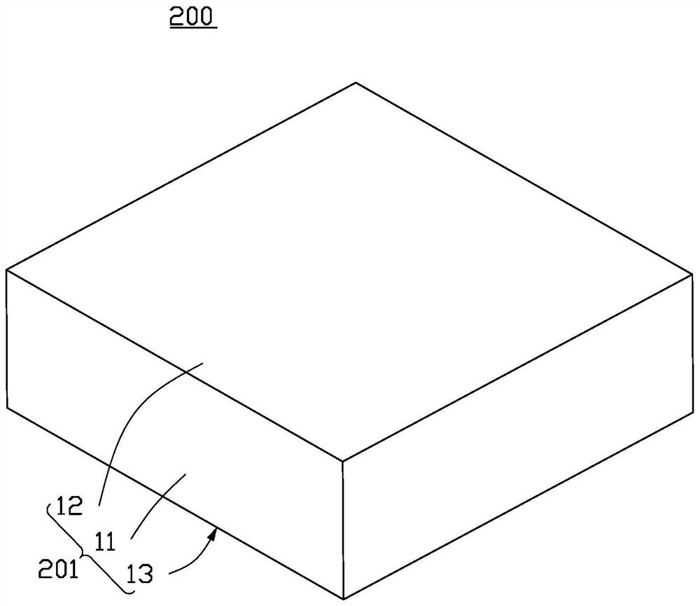
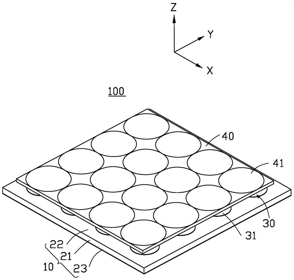
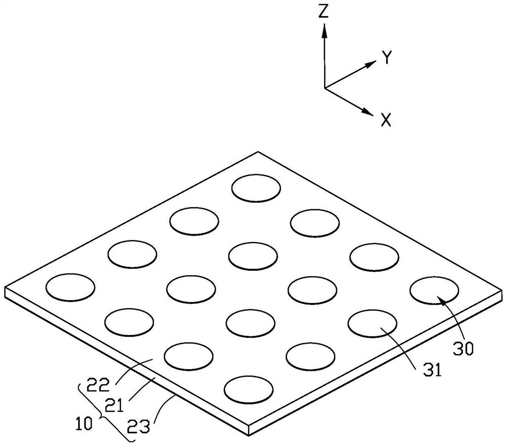
The present invention provides an antenna structure, including a main board and an array antenna, the antenna structure also includes a lens array, the array antenna is arranged on a surface of the main board, the array antenna includes a plurality of antenna units, and the lens array It includes a plurality of lens units, and the plurality of lens units are arranged in one-to-one correspondence with the plurality of antenna units. The present invention also provides a wireless communication device with the antenna structure, including a body and the antenna structure, and the body is used to accommodate the antenna structure.

Description

technical field [0001] The invention relates to an antenna structure and a wireless communication device with the antenna structure. Background technique [0002] In millimeter-wave products, due to the short operating wavelength and large dielectric loss of millimeter-wave microstrip antennas, it is difficult to obtain high-gain antennas and control beam directions simply by using microwave microstrip antenna technology structures. Contents of the invention [0003] In view of this, it is necessary to provide an antenna structure and a wireless communication device with the antenna structure, which can increase the gain of the antenna and control the beam direction. [0004] An embodiment of the present invention provides an antenna structure, the antenna structure includes a main board and an array antenna, the antenna structure also includes a lens array, the array antenna is arranged on a surface of the main board, and the array antenna includes a plurality of For the...

Claims


Application Information

Patent Timeline
Patent Type & Authority Patents(China)
IPC IPC(8): H01Q15/02H01Q21/24H01Q1/50
CPCH01Q21/24H01Q1/50H01Q15/02H01Q21/065H01Q9/0428H01Q15/08H01Q19/062H01Q21/245H01Q15/10H01Q19/06H01Q1/2258H01Q9/06H01Q1/38H01Q21/0025H01Q1/2283H01Q21/0006H01Q21/29
Inventor 陈国丞陈逸名萧翔宇陈益国许锡兴
Owner MOBILE DRIVE NETHERLANDS BV
Learn More