
Self ballasted compact fluorescent lamp and lighting apparatus

A technology for fluorescent lamps and light bulbs, which is applied to lighting devices, components of lighting devices, and energy-saving lighting. Deformation and other problems, to achieve the effect of increasing the surface area, avoiding the rise of the starting voltage, and improving the luminous efficiency

Inactive Publication Date: 2007-12-05
TOSHIBA LIGHTING & TECH CORP
View PDF3 Cites 0 Cited by
  • Summary
  • Abstract
  • Description
  • Claims
  • Application Information

AI Technical Summary

Problems solved by technology

[0005] However, in such a conventional spiral bulb-shaped fluorescent lamp, there is a problem that since the helical end of the spiral luminous tube extends inside the housing and the end of the luminous tube is supported by the fixing portion in the housing, Larger cover size
[0009] Furthermore, when the diameter of the bulb is small, it is not only difficult to mold the straight tubular glass bulb into a spiral shape by using a mold, but also cracks or deformation are likely to occur during the molding process, which will lead to poor quality of the spiral glass bulb in mass production. Downsides of Rate Drop

Method used


Image

  • Self ballasted compact fluorescent lamp and lighting apparatus
  • Self ballasted compact fluorescent lamp and lighting apparatus
  • Self ballasted compact fluorescent lamp and lighting apparatus

Examples


Embodiment Construction

[0072] Hereinafter, embodiments of the present invention will be described with reference to the drawings. In addition, the same code|symbol is attached|subjected to the same or corresponding part in several drawing.

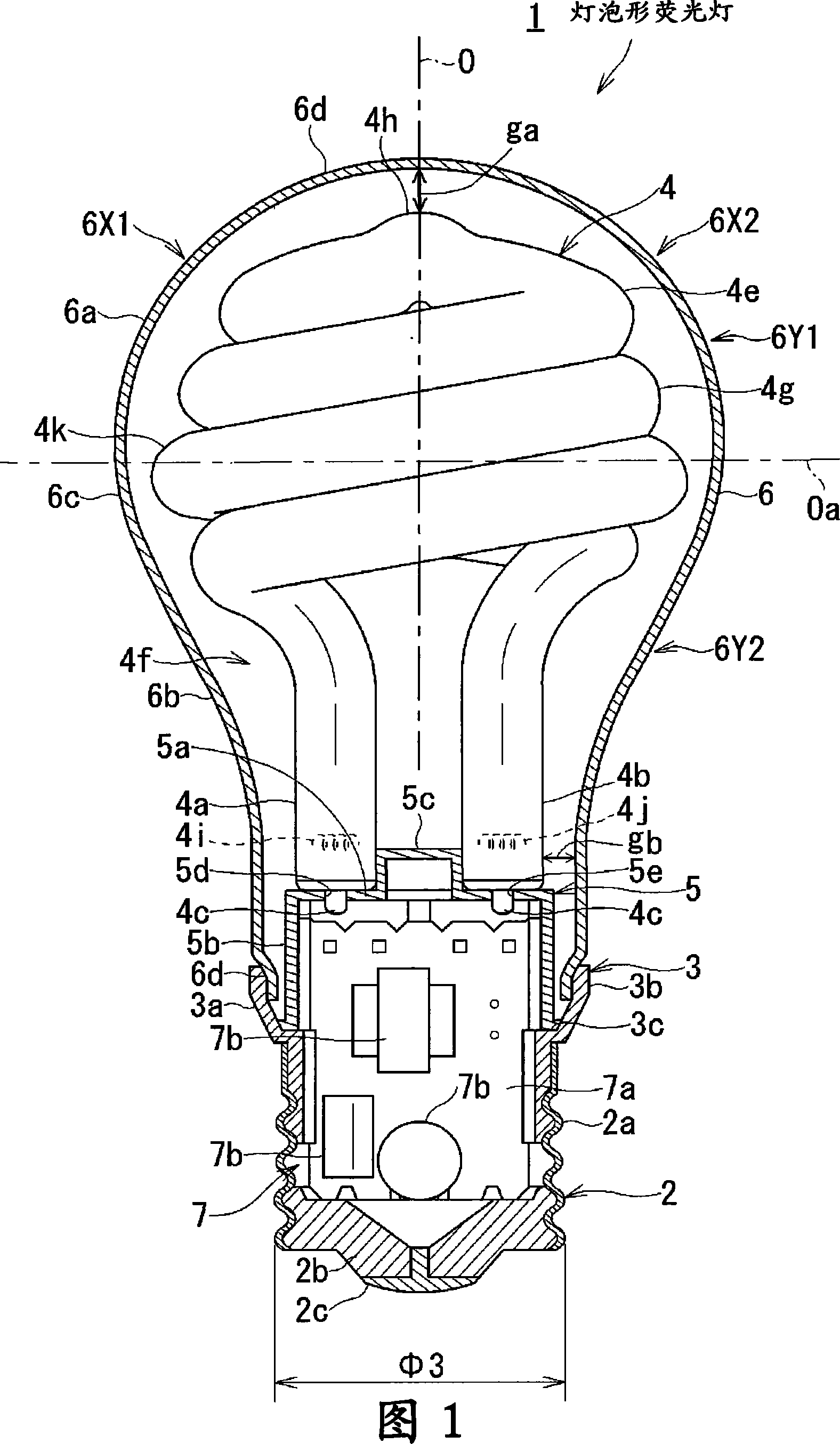
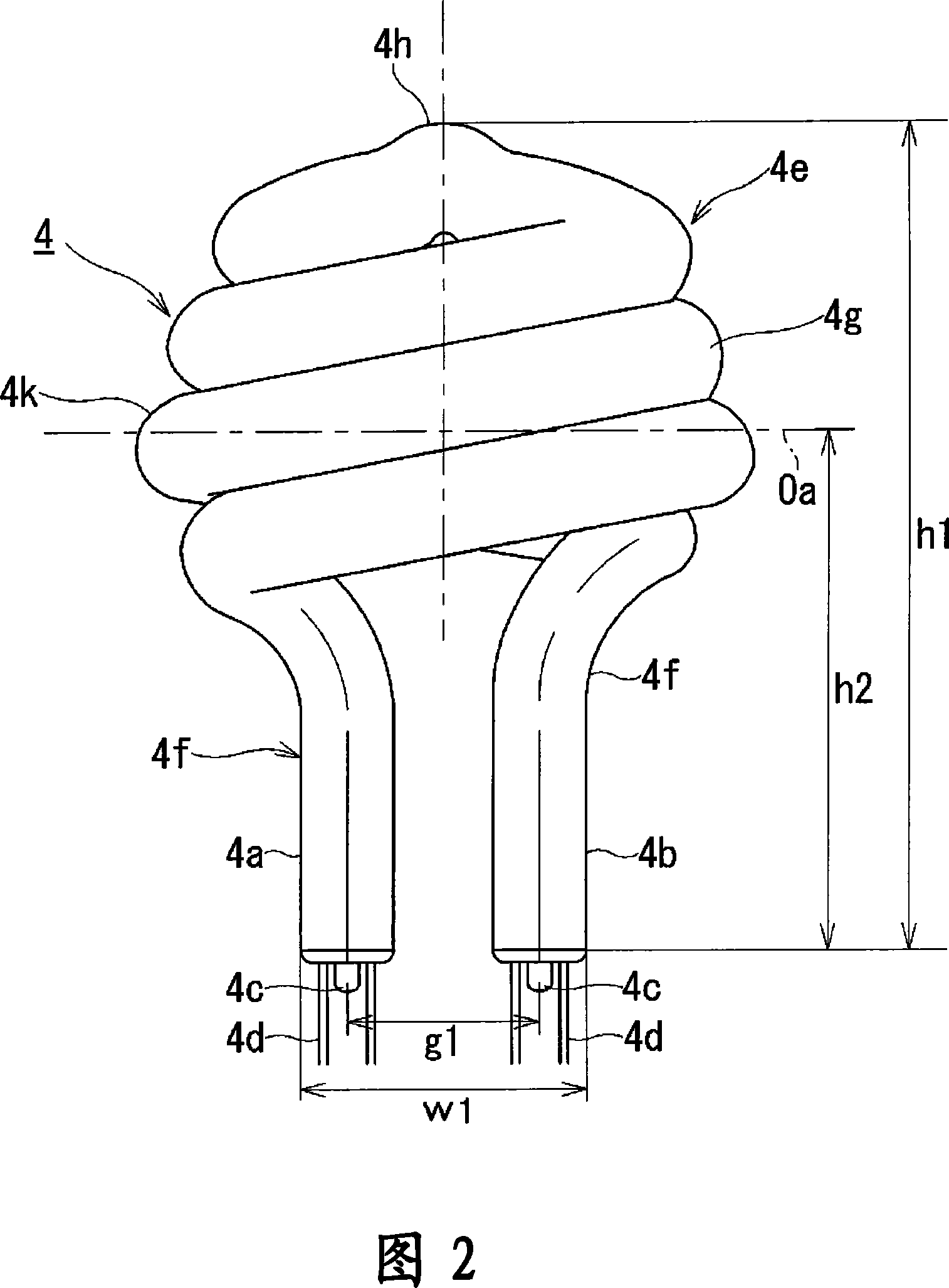
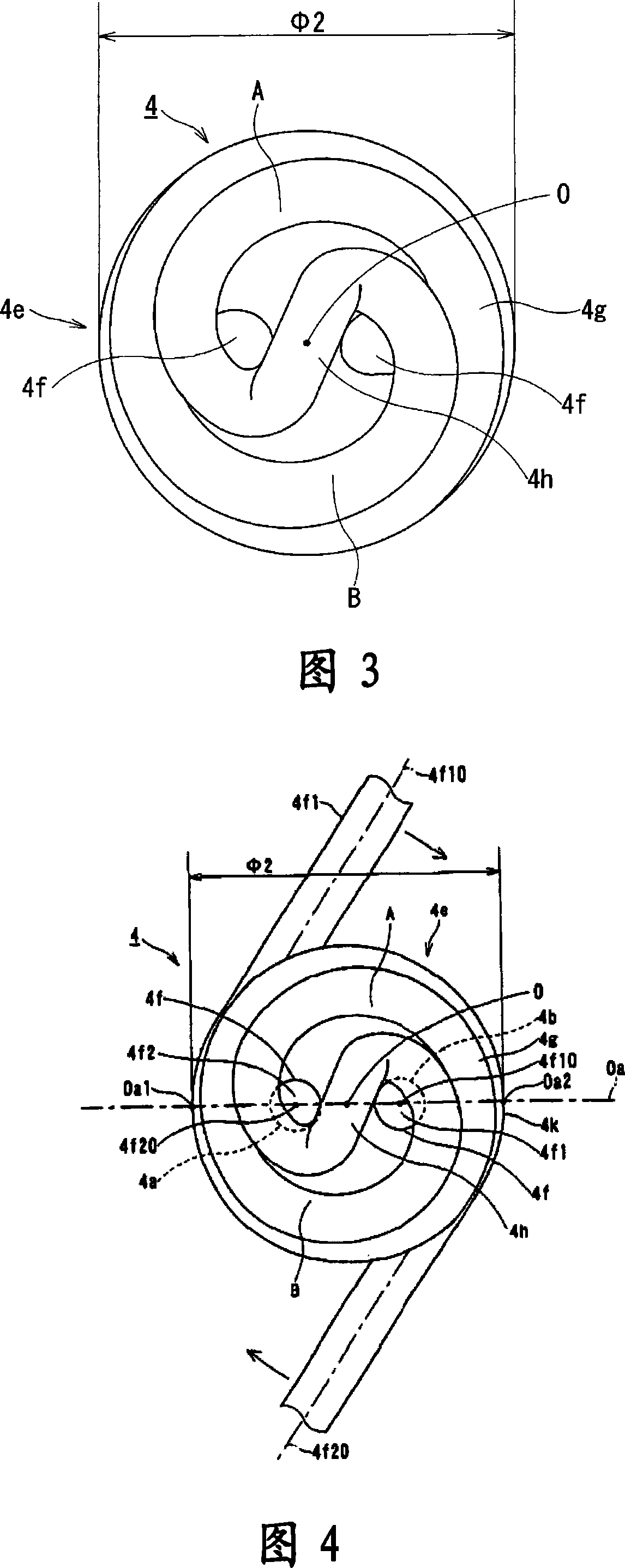
[0073] 1 is a front view showing a part of a bulb-shaped fluorescent lamp and a lighting device according to a first embodiment of the present invention in longitudinal section, FIG. 2 is a front view of the arc tube shown in FIG. 1 , and FIG. 3 is a plan view of the arc tube.

[0074] As shown in FIG. 1, a bulb-shaped fluorescent lamp 1 includes: an outer cover 3 having a lamp holder 2 at one end (lower end in FIG. 1) in a height direction (tube axis direction); ) side supported luminous tube 4; the fixing portion 5 installed on the outer cover 3 supporting the one end side of the luminous tube 4; a lampshade 6; and a lighting device 7 housed inside the lamp socket 2 and the cover 3. Furthermore, the size and appearance of the light bulb-shaped fluorescent la...


PUM


Abstract

To provide a compact self-ballasted fluorescent lamp and a lighting apparatus which can improve light emitting efficiency.The compact self-ballasted fluorescent lamp is provided with a cover 3 with a mouth piece 2, a globe 6 and a glass bulb 4g with a pair of electrodes 4h, 4i housed in the globe, and the bulb is provided with a light-emitting tube 4 which is positioned at a top end part 6d, including a largest diameter part 6c of the globe and is positioned at a spirally formed part 4e and at a narrowed diameter part of the globe, which is formed continuously and integrally with the spirally formed part and is provided with a linear part 4f, including a pair of electrode sealing end parts 4a, 4b, which extend straight in the axial direction, and a lighting unit 7 housed inside the cover.

Description

technical field [0001] The invention relates to a bulb-shaped fluorescent lamp and an illuminating device with the bulb-shaped fluorescent lamp. Background technique [0002] Previously, such bulb-shaped fluorescent lamps have been miniaturized to a size similar to that of a general lighting bulb defined by JIS (Japanese Industrial Standard, Japanese Industrial Standard), and their appearance is similar to that of a general lighting bulb. [0003] This type of bulb-shaped fluorescent lamp includes a luminous tube having a curved bulb, a cover with a lamp socket mounted on one end of the cover body and a luminous tube supported at the other end, a lighting device housed in the cover, and a luminous tube that covers the luminous tube and is installed on the A lampshade and the like on the other end side of the housing (for example, refer to Japanese Patent Application Laid-Open No. 2000-21351). [0004] Moreover, in recent years, a bulb-shaped fluorescent lamp in which a curv...

Claims


Application Information

Patent Timeline
Patent Type & Authority Applications(China)
IPC IPC(8): H01J61/30H01J61/32F21V17/00F21V19/00
CPCH01J61/327Y02B20/19Y02B20/00
Inventor 筏邦彦安田丈夫
Owner TOSHIBA LIGHTING & TECH CORP
Learn More