
Virtual channels for eddy current array probes

a technology of array probes and virtual channels, applied in the field of eddy current array inspection systems, can solve problems such as signal amplitude variation, and achieve the effect of improving probe sensitivity and defect imaging

Active Publication Date: 2018-08-02
OLYMPUS AMERICA +1
View PDF7 Cites 3 Cited by
  • Summary
  • Abstract
  • Description
  • Claims
  • Application Information

AI Technical Summary

Benefits of technology

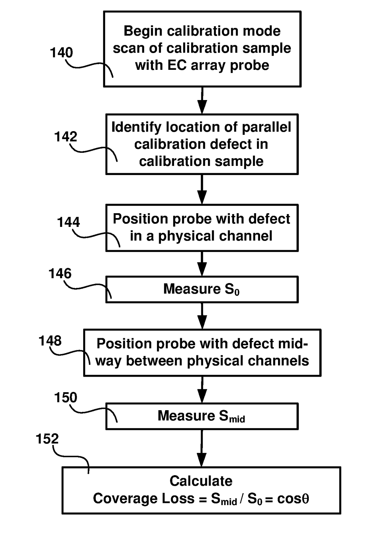
The present patent aims to provide a system and method for reducing coverage loss in Eddy Current Array applications. This is achieved by calculating virtual channels based on the properties of physical channels. The virtual channels can be located mid-way between physical channels and can be used for interpolation of signals from defects located at any position between the physical channels. This improves probe sensitivity and defect imaging as the virtual channels compensate for coverage loss.

Problems solved by technology

A common problem in EC array testing is the signal amplitude variation due to the limited channel coverage of each probe.
However, the interpretation of such signals is based on very specific knowledge of the flaw, and no method is disclosed for creating intermediate virtual channels whose generation is based solely on the physical properties of the coils with no a priori knowledge of the defect being required.

Method used


Image

  • Virtual channels for eddy current array probes
  • Virtual channels for eddy current array probes
  • Virtual channels for eddy current array probes

Examples


Embodiment Construction

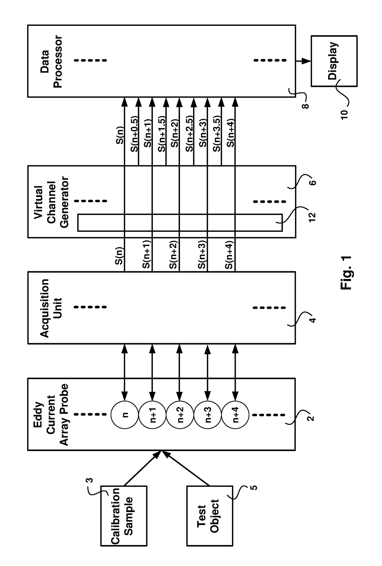
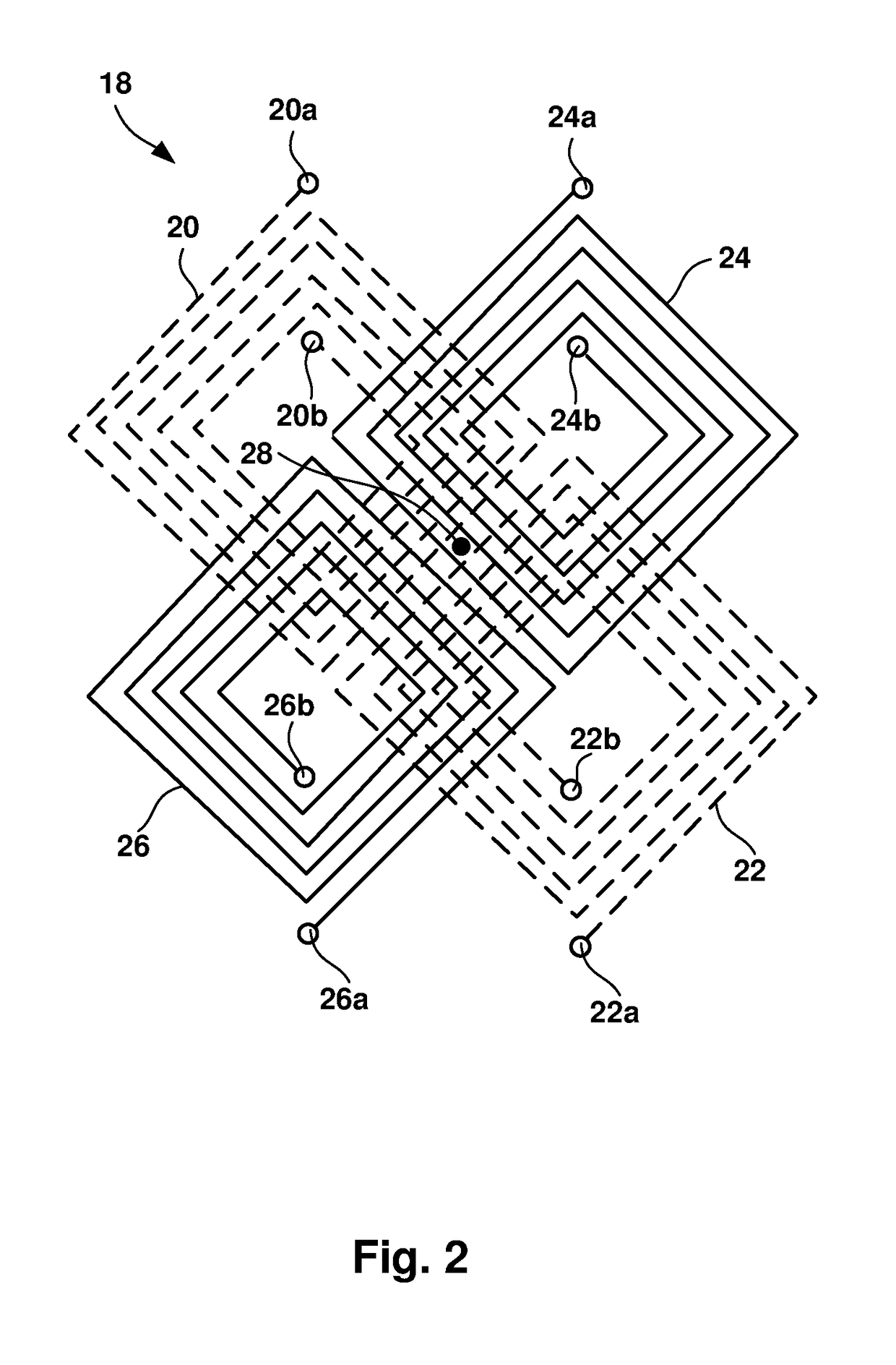
[0024]FIG. 1 is a schematic representation of an EC instrument configured according to the present disclosure. An EC array probe 2 comprises a multiplicity of individual EC sensors, with representative individual EC sensors depicted as circles in the figure and labeled n, n+1, n+2, n+3 and n+4. It is to be understood that each of the representative circles comprises a multiplicity of coils, and any particular coil at a specific time may be configured as a driver coil or as a sensing coil or as both a driver and a sensor. The coil configuration of an exemplary individual EC sensor is shown in FIG. 2.

[0025]Referring again to FIG. 1, EC array probe 2 is configured to be mechanically scanned near the surface of a calibration sample 3 when the EC instrument is in calibration mode, or near the surface of a test object 5 when the EC instrument is in testing mode. An acquisition unit 4 is configured to send commands for energizing the driver coils of each of the individual EC sensors of EC ...


PUM


Abstract

Disclosed is an apparatus and method for generating virtual inspection channels mid-way between the physical inspection channels of an eddy current array probe, thereby reducing the coverage loss and improving defect sizing and imaging. The method is based upon a calibration to determine the mid-channel coverage loss for parallel defects having their long axis parallel to the scanning direction. Based on the coverage loss measurement, a vector analysis system is constructed enabling generation of virtual channel signals which are available for processing in the same way as physical channels, with impedance plane representation including real and / or imaginary signal components. The system differentiates between parallel and perpendicular defects and employs different algorithms to generate virtual channel signals for parallel and perpendicular defect orientations.

Description

FIELD OF THE INVENTION[0001]The invention relates to an eddy current (EC) array inspection system used for non-destructive test and inspection (NDT / NDI), and more particularly to an apparatus and method for improving the reproducibility of EC array systems by generating virtual channels between the physical channels of the EC array.BACKGROUND OF THE INVENTION[0002]The use of EC array probes for NDT / NDI is well known in existing practice. Generally, an EC array probe comprises a multiplicity of individual EC sensors, each individual EC sensor comprising eddy current coils. Some of the coils are configured as driver coils, creating a variable magnetic field in a test object, while other coils are configured as sensing coils which detect magnetic fields generated by eddy currents in the test object. In some embodiments, the same coil can simultaneously serve both driver and sensing functions. Each individual EC sensor has a center point where there is maximum sensitivity to eddy curren...

Claims


Application Information

Patent Timeline
IPC IPC(8): G01N27/90
CPCG01N27/9046G01N27/904G01N27/82G01N27/90G01N27/9053
Inventor LEPAGE, BENOIT
Owner OLYMPUS AMERICA
Learn More