Robust Control Channel Transmission Scheme

a transmission scheme and control channel technology, applied in the field of wireless communication, can solve problems such as too long delay

Active Publication Date: 2018-08-09
NOKIA TECHNOLOGLES OY
View PDF9 Cites 32 Cited by
  • Summary
  • Abstract
  • Description
  • Claims
  • Application Information

AI Technical Summary

Benefits of technology

[0023]An exemplary embodiment is an apparatus. The apparatus comprises at least one processor and at least one memory tangibly storing a computer program. The at least one processor is configured with the at least one memory and the computer program to cause the apparatus to: receive signaling to configure a user equipment (UE) with multiple transmit beams each for receiving beam-specific downlink control information (DCI); receive a beam-specific current DCI at the UE on at least one of the transmit beams, said received current DCI including information about beam-specific previous DCIs transmitted to the UE on any of the multiple transmit beams within a predefined time window preceding a time unit in which the current DCI was received; use the information about the beam-specific previous DCIs to determine that at least one of the multiple transmit beams has been blocked; and report each of the multiple transmit beams that have been determined to be blocked.
[0024]Another exemplary embodiment is a method. The method comprises the following: receiving signaling to configure a user equipment (UE) with multiple transmit beams each for receiving beam-specific downlink control information (DCI); receiving a beam-specific current DCI at the UE on at least one of the transmit beams, said received current DCI including information about beam-specific previous DCIs transmitted to the UE on any of the multiple transmit beams within a predefined time window preceding a time unit in which the current DCI was received; using the information about the beam-specific previous DCIs to determine that at least one of the multiple transmit beams has been blocked; and reporting each of the multiple transmit beams that have been determined to be blocked.
[0025]A further exemplary embodiment is a computer readable memory tangibly storing a computer program that when executed causes a host radio network access node to perform a method comprising the following: receiving signaling to configure a user equipment (UE) with multiple transmit beams each for receiving beam-specific downlink control information (DCI); receiving a beam-specific current DCI at the UE on at least one of the transmit beams, said received current DCI including information about beam-specific previous DCIs transmitted to the UE on any of the multiple transmit beams within a predefined time window preceding a time unit in which the current DCI was received; using the information about the beam-specific previous DCIs to determine that at least one of the multiple transmit beams has been blocked; and reporting each of the multiple transmit beams that have been determined to be blocked.
[0026]A further example is an apparatus. The apparatus comprises at least one processor and at least one memory tangibly storing a computer program; wherein the at least one processor is configured with the at least one memory and the computer program to cause the apparatus to: configure a user equipment (UE) with multiple transmit beams each for receiving beam-specific downlink control information (DCI); transmit to the UE a beam-specific current DCI on at least one of the transmit beams, said transmitted current DCI including information about beam-specific previous DCIs transmitted to the UE on any of the multiple transmit beams within a predefined time window preceding a time unit in which the current DCI was received; and in response to receiving from the UE a report indicating at least one multiple transmit beams has been determined to be blocked, reconfigure the UE with a different set of multiple transmit beams each for beam-specific DCI.

Problems solved by technology

But if instead a given PDCCH did schedule the UE and the UE did not properly receive it, for example due to blockage of the beam that was to carry it, the UE would also not signal the network for it does not know it missed a PDCCH.
But this is too long of a delay, particularly in a NR / 5G type radio environment where the viable beams for a UE may change rapidly.

Method used


Image

  • Robust Control Channel Transmission Scheme
  • Robust Control Channel Transmission Scheme
  • Robust Control Channel Transmission Scheme

Examples


Embodiment Construction

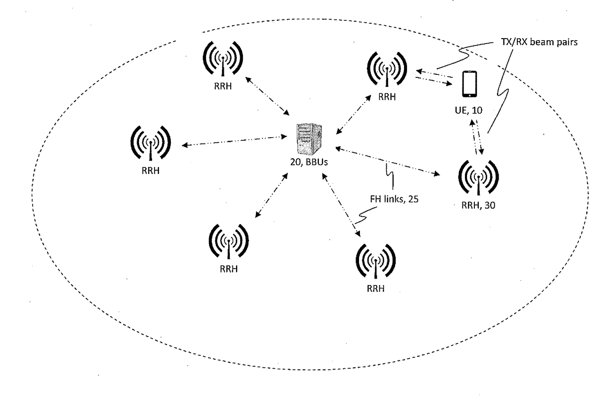
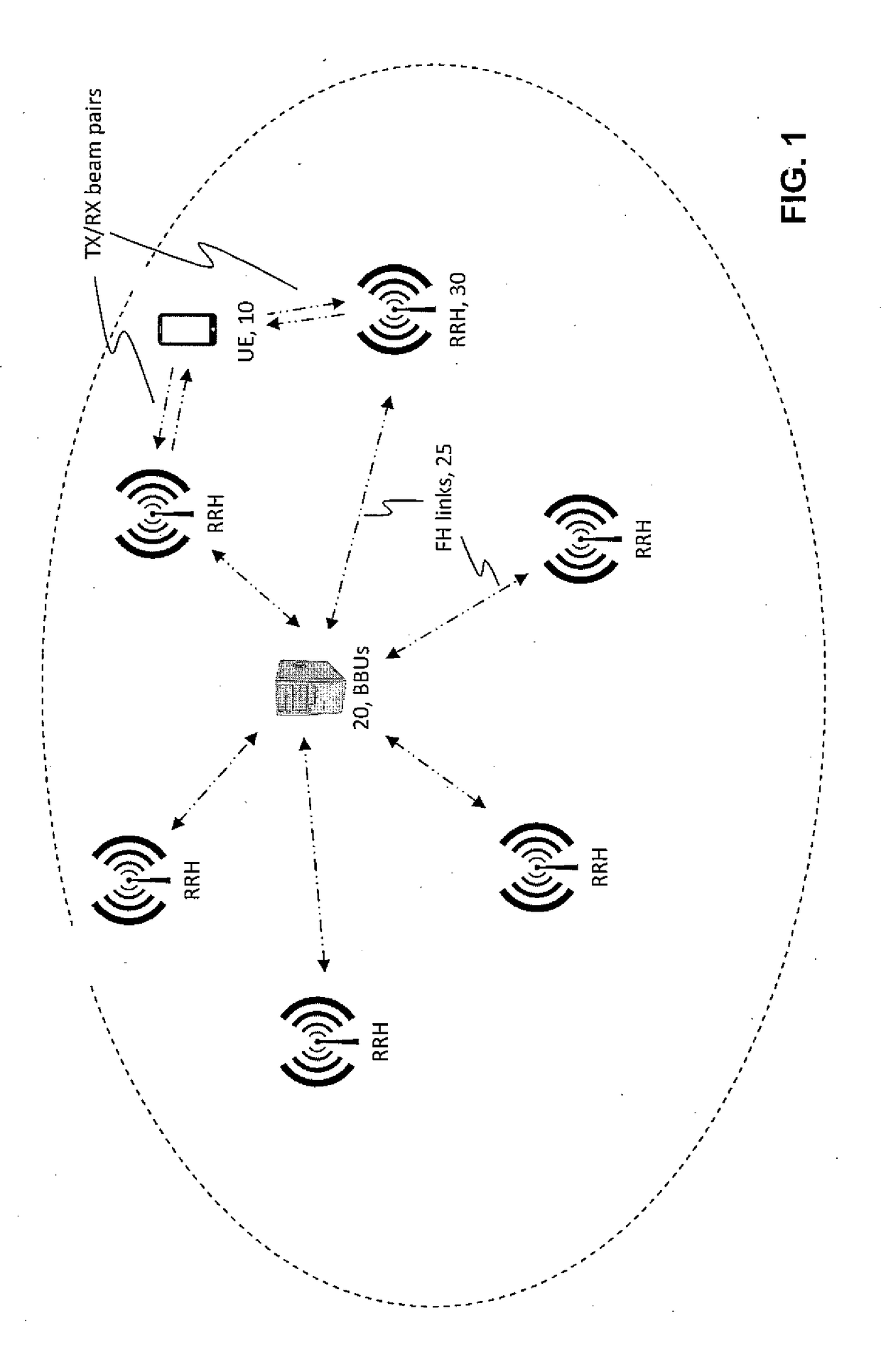
[0029]The embodiments below are in the context of a NR / 5G radio system but this is only an example radio environment and not a limit to the broader teachings herein. Since these teachings are directed primarily to the exchange between the radio network and the UE, the network side of this exchange will be described with reference to a TRP, which per FIG. 1 may be RRHs but not all TRPs are RRHs.

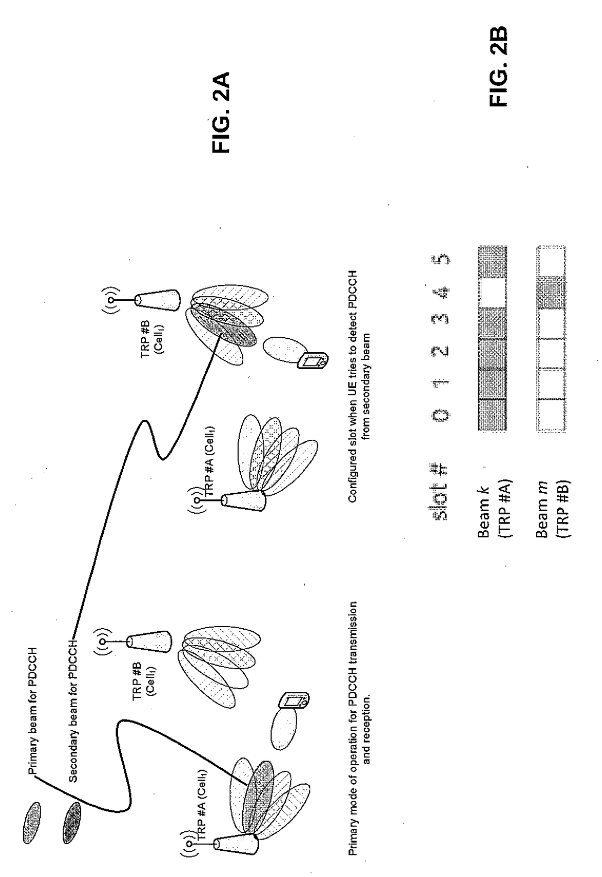
[0030]Given the sensitivity to beam blockage at mmWave frequencies in general, in the 3GPP group's development of NR / 5G it is already being considered to make the NR-PDCCH more robust by enabling it to be transmitted to the UE from multiple TRPs, meaning multiple beams. Further refining this in view of the fact that not all UEs may be capable of ‘listening’ simultaneously in multiple directions, a time domain pattern for the PDCCH beams is being considered so that the UE is able to know which beam would be the transmitting beam for PDCCH at a certain slot. On the other band, this beam blockage...


PUM


Abstract

Signaling is received (or transmitted) to configure a UE with multiple transmit beams, each for receiving beam-specific DCI. A beam-specific current DCI is received at the UE (or transmitted from a network) on the transmit beam(s), including information about beam-specific previous DCIs transmitted to the UE on any of the multiple transmit beams within a predefined time window preceding a time unit in which the current DCI was received. Information about the beam-specific previous DCIs is used to determine that at least one of the multiple transmit beams has been blocked. Each of the multiple transmit beams that have been determined to be blocked is reported to (and received by) the network. In response to receiving from the UE a report indicating at least one multiple transmit beams has been blocked, the network reconfigures the UE with a different set of multiple transmit beams each for beam-specific DCI.

Description

CROSS-REFERENCE TO RELATED APPLICATIONS[0001]The present application claims the benefit under 35 U.S.C. § 119(e) of U.S. Provisional Patent Application No. 62 / 455,094, filed on Feb. 6, 2017, the disclosure of which is hereby incorporated by reference in its entirety.TECHNOLOGICAL FIELD[0002]The described invention relates to wireless communications, and more particularly to control channel signaling that can be used to identify a blocked beam in a radio environment in which a user equipment (UE) has connections with multiple transmit-receive points (TRPs) over multiple beams.BACKGROUND[0003]Wireless radio access technologies continue to be improved to handle increased data volumes and larger numbers of subscribers. The 3GPP organization is developing a new radio system (commonly referred to as NR or 5th Generation / 5G) to handle peak data rates of the order of ˜10 Gbps (gigabits per second) while still satisfying ultra-low latency requirements in existence for certain 4G applications...

Claims


Application Information

Patent Timeline
Patent Type & Authority Applications(United States)
IPC IPC(8): H04W72/04
CPCH04W72/042H04W72/046H04W74/0833H04B7/022H04B7/0408H04B7/0617H04B7/0695H04W72/23
Inventor HAKOLA, SAMI-JUKKATIIROLA, ESA T.ENESCU, MIHAIKAIKKONEN, JORMAKARJALAINEN, JUHA P.
Owner NOKIA TECHNOLOGLES OY
Why Eureka
Try Eureka