Method and apparatus for conveying articles, piece goods and/or containers within at least two conveying path sections

a technology of conveying path and conveyor line, which is applied in the directions of stacking articles, packaging, loading/unloading, etc., to achieve the effect of high capacity and compactness and efficiency

Active Publication Date: 2018-08-16
KRONES AG
View PDF13 Cites 11 Cited by
  • Summary
  • Abstract
  • Description
  • Claims
  • Application Information

AI Technical Summary

Benefits of technology

[0011]In this apparatus, a lifting column, for example, with vertically adjustable guiding devices for being able to perform the lifting and lowering of the at least two support surfaces and / or conveying surfaces independently of one another can be associated with the loading station or, as the case may be, with the transfer stations and with their at least two vertically adjustable support surfaces and / or conveying surfaces arranged upstream from the loading station. Other configurations are optionally possible, a lifting column, however, can provide a particularly compact and efficient possibility for lifting and / or conveying the article layers, piece good layers, and / or bundle layers to be palletized. When using such a lifting column or also two or more lifting columns, it can be provided that the support surfaces and / or conveying surfaces are suspended by way of traction means, such as straps, from the lifting column and are arranged thereat to be vertically motor-movable. For this purpose, electric motors can be arranged at the upper side of the lifting column, for example, to serve as drives for the liftable and lowerable support surfaces and / or conveying surfaces.
[0013]In an alternative arrangement, the conveying direction of at least one of the support surfaces and / or conveying surfaces to the loading place can be optionally oriented substantially parallel to or aligned with the removal direction of a finished / completed palletized stack of a plurality of article layers, piece good layers, and / or bundle layers deposited on top of each other. Here, the in each case other conveying direction can likewise be oriented parallel to or aligned with the removal direction. Other, different orientations are equally possible so that space-saving and very flexible configurations are made possible, for example in spatially confined machine environments.
[0014]In all variants of the palletizing apparatus according to the invention, the loading place can in particular have at least one horizontal conveying element or, as the case may be, at least one such horizontal conveying element can be associated with the loading place, which horizontal conveying element is oscillatingly movable between the at least two adjustable support surfaces and / or conveying surfaces. This at least one horizontal conveying element can expediently be formed by a circulating modular conveyor belt. Optionally, the at least one horizontal conveying element can also be formed by a movable shutter element or the like, supplemented with movable braking elements and / or holding elements, as the case may be, such that transferred article layers or bundle layers can be fixed or held together in their particular layer formations. Transfer elements, such as push bars contacting from the rear, can also be used as horizontal conveying elements. In this instance, the support surface is as smooth and low-resistance as possible such that the layers to be palletized will easily slide on it. For the purpose of supporting transferred article layers, piece good layers, and / or bundle layers, it can be moreover expedient for many configurations to associate a contact element, such as a so-called braking bar, which is usable alternately for two transfer directions, with the at least one horizontal conveying element. Such a contact element or, as the case may be, such a braking bar can effectively prevent the layer formation from becoming undone or the articles, piece goods, or bundles of a layer from slightly shifting or even falling over in quick transfer or in a quick feed movement of the modular conveyor belt or of the shutter element.

Problems solved by technology

Since each vertical movement of each transfer station requires time, it is not the actual palletizing, but rather the transfer of the article layers from the grouping stations to the proper depositing location and the vertical positioning of said article layers that usually form the limiting factors for the performance of such a machine.

Method used


Image

  • Method and apparatus for conveying articles, piece goods and/or containers within at least two conveying path sections
  • Method and apparatus for conveying articles, piece goods and/or containers within at least two conveying path sections
  • Method and apparatus for conveying articles, piece goods and/or containers within at least two conveying path sections

Examples


first embodiment

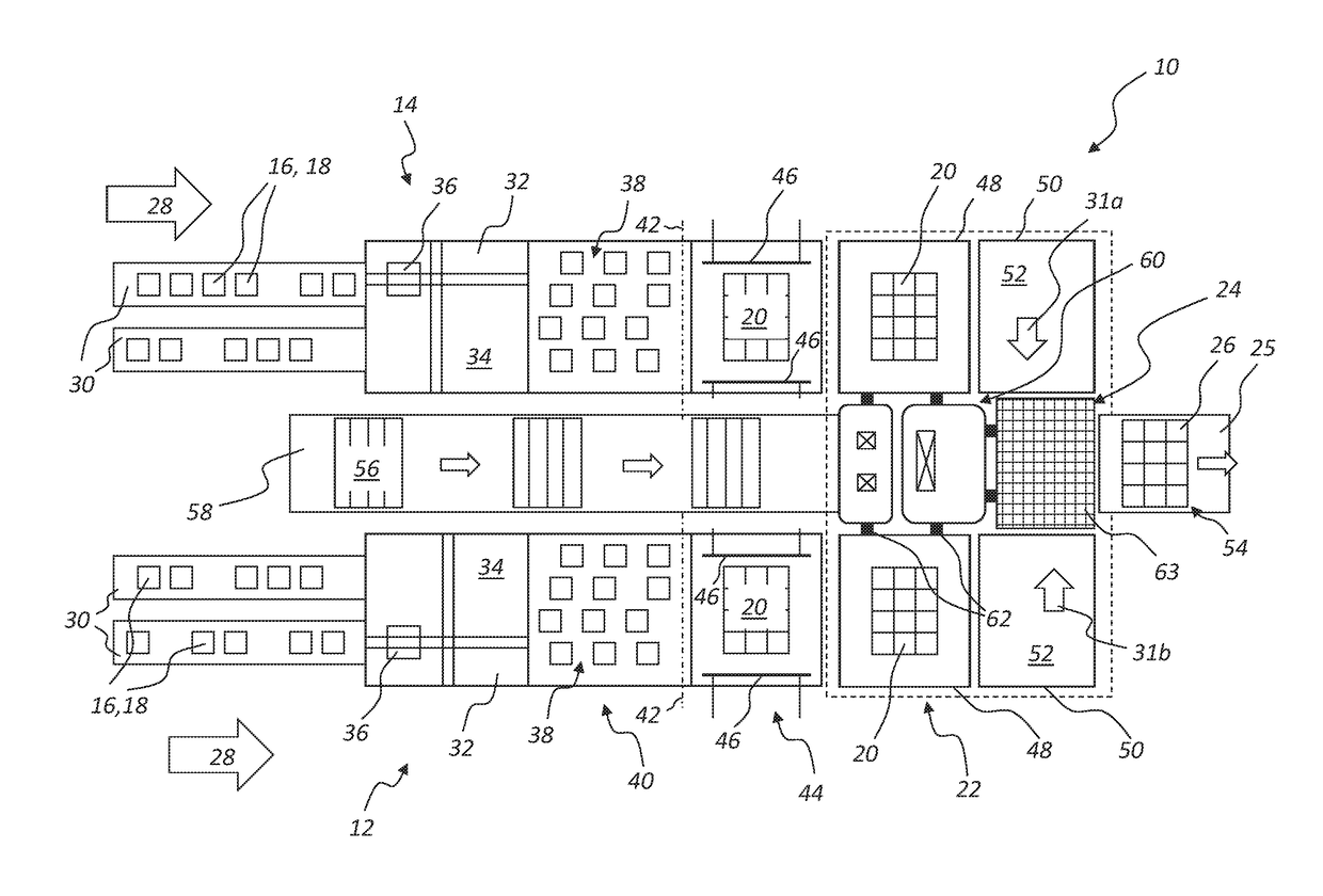
[0030]The schematic top view of FIG. 1 illustrates a possible configuration of a first embodiment variant of a conveying apparatus, grouping apparatus, and / or palletizing apparatus 10 according to the invention and comprising as central components two parallel-running conveyor line sections 12 and 14, which each serve for conveying articles 16, piece goods, and / or bundles 18, as well as for combining and assembling them to form palletizable layers 20, and which lead into a common palletizing unit 22, which is illustrated in the shown exemplary embodiment of FIG. 1 framed by a broken line on the right side of the palletizing apparatus 10. An important component of the palletizing unit 22 or of this common palletizing station is a central loading station 24, which provides for stacking and palletizing the particular article layers or bundle layers 20 onto one single common loading place 25 to form a common stack 26 of layers 20 layered on top of each other. The stack 26 can take diffe...

second embodiment

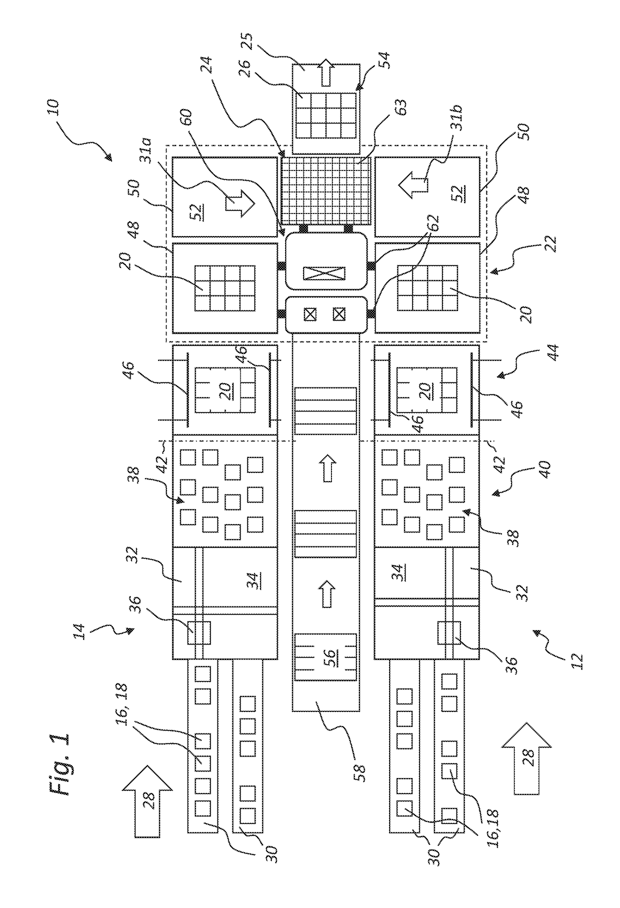
[0041]The FIG. 2 shows a further schematic top view onto a second embodiment variant of the conveying apparatus, grouping apparatus, and / or palletizing apparatus 10 according to the invention, which is provided with additional devices 64 for feeding intermediate layers to the loading place 25. The intermediate layers 66 are in each case removed from intermediate layer stacks by means of rotatably movable handling devices 68, such as grippers or the like, and deposited on each individual, deposited layer 20 on the stack 26, or optionally on every other or every third layer 20, whereby the stack 26 is mechanically stabilized and the individual articles 16 or bundles 18 are prevented from shifting or tilting. In the remaining conveying process, the palletizing apparatus 10 shown in FIG. 2 largely corresponds to the palletizing apparatus shown in FIG. 1. Therefore, if in the following description of FIG. 2 individual details or elements that are designated with reference characters are ...

third embodiment

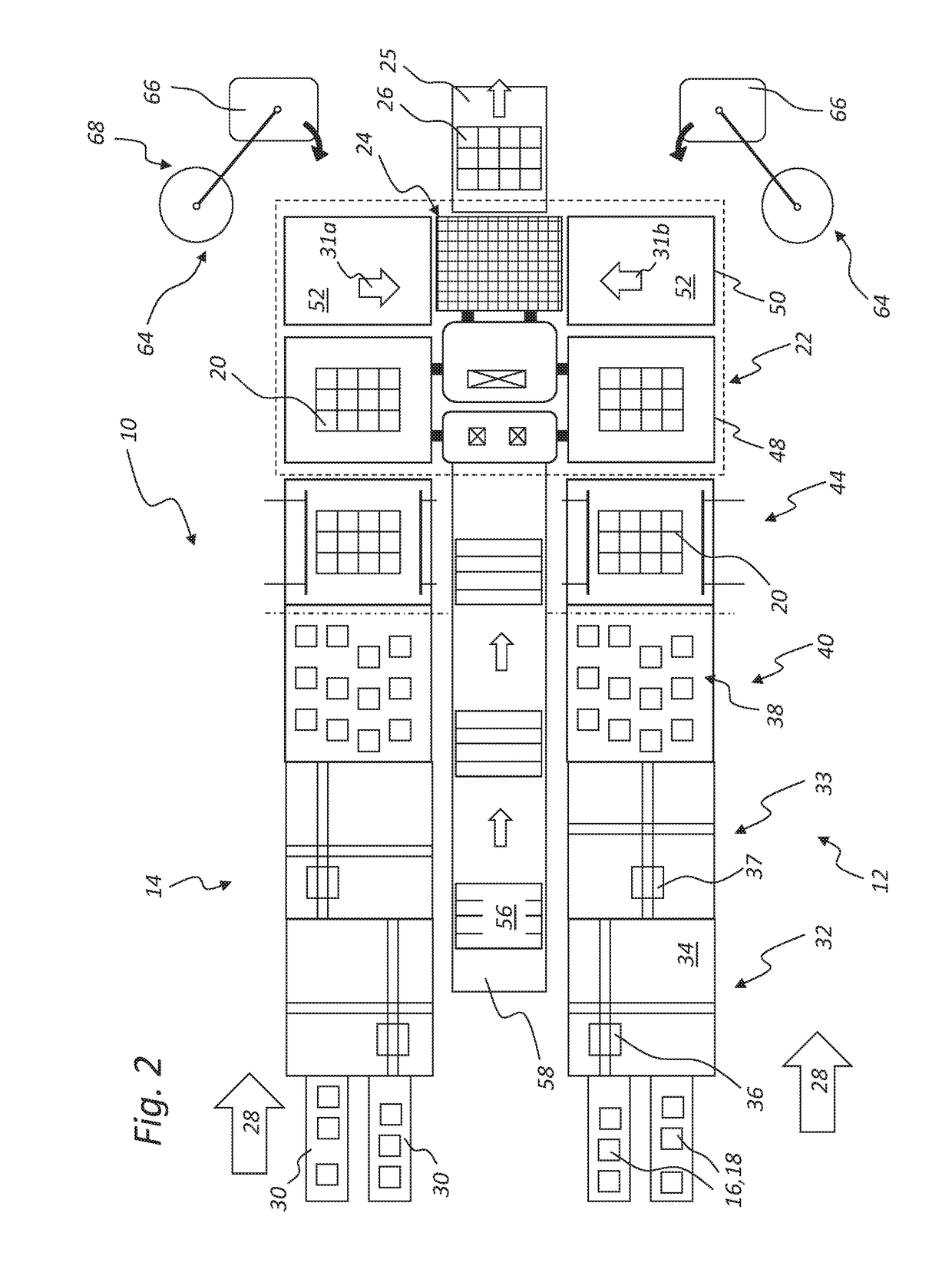
[0046]The FIG. 3 shows a schematic top view onto a third embodiment variant of the palletizing apparatus 10 according to the invention provided with an alternative handling device 70 for the linear feeding of intermediate layers 66 to the loading place 25. In this context, the intermediate layers 66 are preferably removed from at least one intermediate layer stack 72 and individually fed to the stack 26 standing on the loading place 25 such that in each case an intermediate layer 66 is placed onto each layer 20 or onto every other or every third layer 20. In the remaining conveying process, the palletizing apparatus 10 shown in FIG. 3 largely corresponds to the palletizing apparatus 10 as shown in FIG. 2. Intermediate layers 66 can optionally be fed from both sides by handling devices 70 operating in each case in a linear manner, for example when the grouped article layers or bundle layers 20 located on the second transfer stations 50 are already to be provided with individual inter...


PUM


Abstract

The invention relates to a palletizing apparatus (10) and a method for conveying articles (16), piece goods, and / or bundles (18) and / or palletizable article layers, piece good layers, and / or bundle layers (20) with at least two conveyor line sections (12, 14), each in a particular conveying direction (28, 29). Each conveyor line sections include consecutive handling stations, grouping stations, and / or transfer stations (32, 33, 40, 44, 48, 50), which lead to a central loading station (24), where the article layers, piece good layers, and / or bundle layers (20) are stacked on top of each other and / or palletized in a common loading place (25). The loading station (24) is located between at least two vertically adjustable support surfaces and / or conveying surfaces (52). The common loading place (25) is supplied with article layers, piece good layers, and / or bundle layers (20).

Description

CLAIM OF PRIORITY[0001]The present application is a national stage application of International Application PCT / EP2015 / 075455, filed Nov. 2, 2015, which in turn claims priority to German Application DE 10 2014 223 319.4, filed Nov. 14, 2014, all of which are incorporated by reference.FIELD OF THE INVENTION[0002]The present invention relates to a palletizing apparatus of at least two conveyor line sections for conveying articles, piece goods, and / or bundles and / or palletizable article layers, piece good layers, and / or bundle layers.[0003]The invention moreover relates to a method for conveying articles, piece goods, and / or bundles and / or palletizable article layers, piece good layers, and / or bundle layers within at least two conveyor line sections.BACKGROUND OF THE INVENTION[0004]In known packaging and palletizing facilities, articles, packages, and piece goods are conveyed on transport tracks and shifted or aligned in a manner suitable for producing desired layer patterns, which can...

Claims


Application Information

Patent Timeline
Patent Type & Authority Applications(United States)
IPC IPC(8): B65G57/10B65G57/06B65G65/02
CPCB65G57/10B65G57/06B65G65/02B65G2203/0225B65G2203/0233B65G2207/14B65G57/24B65G47/086
Inventor KOLLMUSS, MANUELESCHLBECK, RICHARD
Owner KRONES AG
Why Eureka
Try Eureka