Supercharge Your Innovation With Domain-Expert AI Agents!

Turbine blade having a tip shroud notch

a turbine blade and tip shroud technology, applied in the direction of machines/engines, sustainable transportation, mechanical equipment, etc., can solve the problems of increasing the complexity and expense of manufacturing the tip shroud, affecting the creep rate of the turbine blade, and limited the operation life cycle of the tip shroud of the turbine blade at least some latter stag

Active Publication Date: 2018-08-16
GENERAL ELECTRIC CO
View PDF26 Cites 6 Cited by
  • Summary
  • Abstract
  • Description
  • Claims
  • Application Information

AI Technical Summary

Benefits of technology

The patent describes various turbine blade designs with improved tip shrouds. These designs have a pressure side edge with a notch or a smooth, continuous arcuate profile that blends into the radially outer edge of the notch. The technical effect of these improvements is increased efficiency and performance of the turbine blade. Additionally, the thickness of the tip shroud at certain locations is designed to optimize its strength and durability.

Problems solved by technology

An operational life cycle of at least some latter stage turbine blade tip shrouds may be limited by creep.
Turbine shroud creep rate may be greatly impacted by the high temperatures often seen at the shroud.
However, known tip shroud core plenums generally increase the complexity and expense of manufacture of the tip shroud, and impose design limits on other properties of the shroud, such as shape and thickness.
However, an ability to reduce the shroud area is limited by a need for the shrouds to cooperate structurally with adjacent shrouds.

Method used


Image

  • Turbine blade having a tip shroud notch
  • Turbine blade having a tip shroud notch
  • Turbine blade having a tip shroud notch

Examples


Embodiment Construction

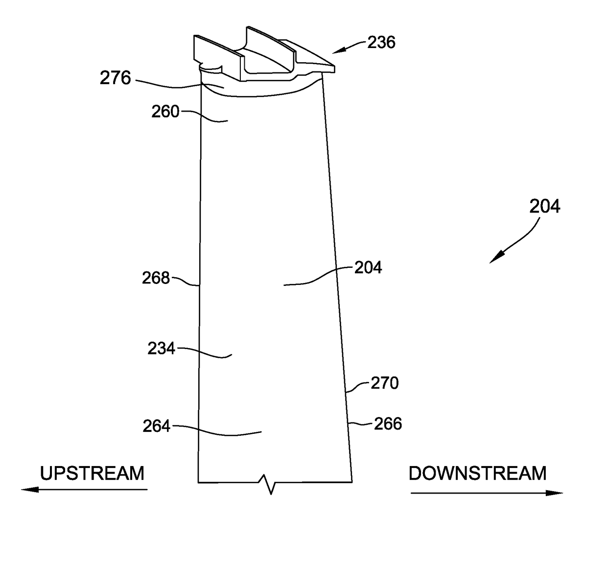
[0013]The exemplary methods and systems described herein overcome at least some disadvantages of known turbine blades by providing a tip shroud that includes a shroud plate having a notch defined along a pressure side edge. In some embodiments, a primary contact surface of the pressure side edge is configured to couple against an adjacent tip shroud, and the notch extends at least partially downstream from the primary contact surface. In particular, in some such embodiments, a specific shape of the notch enables a local shroud plate thickness along the primary contact surface and / or an upstream edge of the notch to be increased. Additionally or alternatively, the tip shroud includes a leading shroud rail and a second, downstream shroud rail, and a downstream pressure side edge of the second rail blends into a radially outer edge of the notch in a smooth, continuous arcuate profile. Additionally or alternatively, a local shroud plate thickness of at least a first location along an up...


PUM


Abstract

A turbine blade includes an airfoil that extends from a root end to a tip end, and a tip shroud extending from the tip end. The tip shroud includes a shroud plate that includes a pressure side edge. The pressure side edge includes a primary contact surface configured to couple against an adjacent tip shroud, and a notch extending at least partially downstream from the primary contact surface.

Description

BACKGROUND OF THE INVENTION[0001]The field of the disclosure relates generally to rotary machines, and more particularly, to a tip shroud of a turbine blade that includes notch features.[0002]At least some known rotary machines include a compressor, a combustor coupled downstream from the compressor, a turbine coupled downstream from the combustor, and a rotor shaft rotatably coupled between the compressor and the turbine. Some known turbines include at least one rotor disk coupled to the rotor shaft, and a plurality of circumferentially-spaced turbine blades that extend outward from each rotor disk to define a stage of the turbine. Each turbine blade includes an airfoil that extends radially outward from a platform towards a turbine casing.[0003]At least some known turbine blades include a shroud that extends from an outer tip end of the airfoil to reduce gas flow leakage between the airfoil and the turbine casing. An operational life cycle of at least some latter stage turbine bla...

Claims


Application Information

Patent Timeline
IPC IPC(8): F01D5/20F01D11/08F01D25/24
CPCF01D5/20F01D11/08F05D2260/30F05B2240/11F01D25/24F01D5/225F05D2240/81F05D2260/20Y02T50/60
Inventor ZEMITIS, WILLIAM SCOTTPILSON, RICHARD RYANMYERS, MELBOURNE JAMES
Owner GENERAL ELECTRIC CO
Features
  • R&D
  • Intellectual Property
  • Life Sciences
  • Materials
  • Tech Scout
  • Unparalleled Data Quality
  • Higher Quality Content
  • 60% Fewer Hallucinations
Learn More