Radially applied dog clutch with bi-directional ratcheting for a vehicle transmission

a transmission and ratcheting technology, applied in the direction of clutches, interlocking clutches, clutches, etc., can solve the problems of reducing fuel economy, and affecting the efficiency of a vehicle, so as to spin losses, and reduce the noise of ratcheting. the effect of noise reduction

Active Publication Date: 2018-08-16
GM GLOBAL TECH OPERATIONS LLC
View PDF0 Cites 0 Cited by
  • Summary
  • Abstract
  • Description
  • Claims
  • Application Information

AI Technical Summary

Benefits of technology

[0027]In this manner, the present invention provides all of the advantages of a dog clutch over a friction clutch (obviating friction losses and pumping losses) while enabling an easier, more consistent, more controllable, and reliable disengagement and minimizing or preventing ratcheting noises and spin losses, thereby significantly improving efficiency, fuel economy and reducing noise.
[0028]Further, exemplary embodiments of the present invention provide the ability to minimize or prevent potential damage in an overload condition and also to control multiple radially applied dog clutches using a single actuator which can greatly simplify operation, reduce size and cost.

Problems solved by technology

Friction clutches suffer from spin losses and pump losses.
The energy consumed by the pump(s) that provide the source for high pressure hydraulic fluid can adversely affect the efficiency of a vehicle incorporating a transmission that includes friction clutches and, thus, reduce its fuel economy.
Rather, a dog clutch relies upon interference between components of the clutch.
Another disadvantage with a dog clutch is that they may be difficult to disconnect or disengage, especially while under load.
This results in undesirable contact between these teeth and the outer driven teeth which may be a significant source of noise (ratcheting noise) and a cause for spin losses which adversely affects the overall efficiency of the system and resulting loss in fuel economy.

Method used


Image

  • Radially applied dog clutch with bi-directional ratcheting for a vehicle transmission
  • Radially applied dog clutch with bi-directional ratcheting for a vehicle transmission
  • Radially applied dog clutch with bi-directional ratcheting for a vehicle transmission

Examples


Embodiment Construction

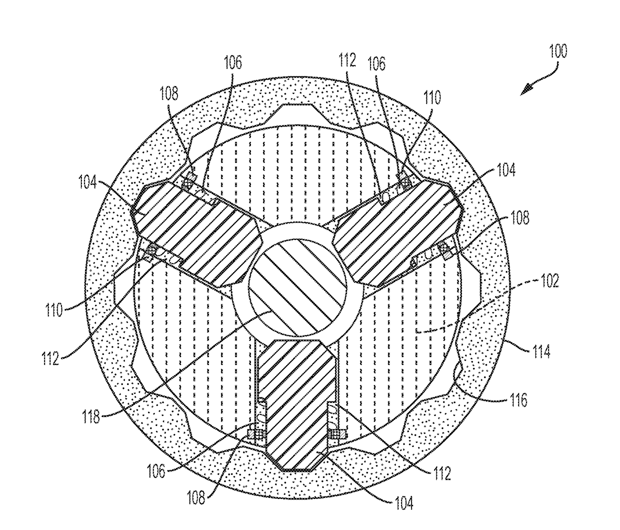
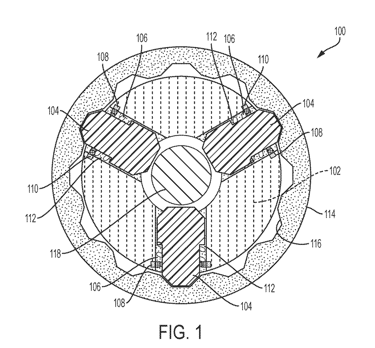
[0039]FIG. 1 is a cross-sectional view in an axial direction of an exemplary dog clutch 100 in accordance with the present invention. The dog clutch 100 includes a driving member 102 supporting radially movable teeth 104. Each tooth 104 is biased radially inwardly by a biasing member 106. In the particular embodiment illustrated by FIG. 1, the biasing members 106 are helically coiled springs which are captured between spring retainer 108, which are each positioned within a groove 110 in the driving member 102 circumferentially surrounding each corresponding tooth 104, and a landing 112 on each tooth. The dog clutch 100 further includes a driven member 114 with a plurality of radially inwardly facing driven teeth 116 and a selectively actuatable actuator 118.

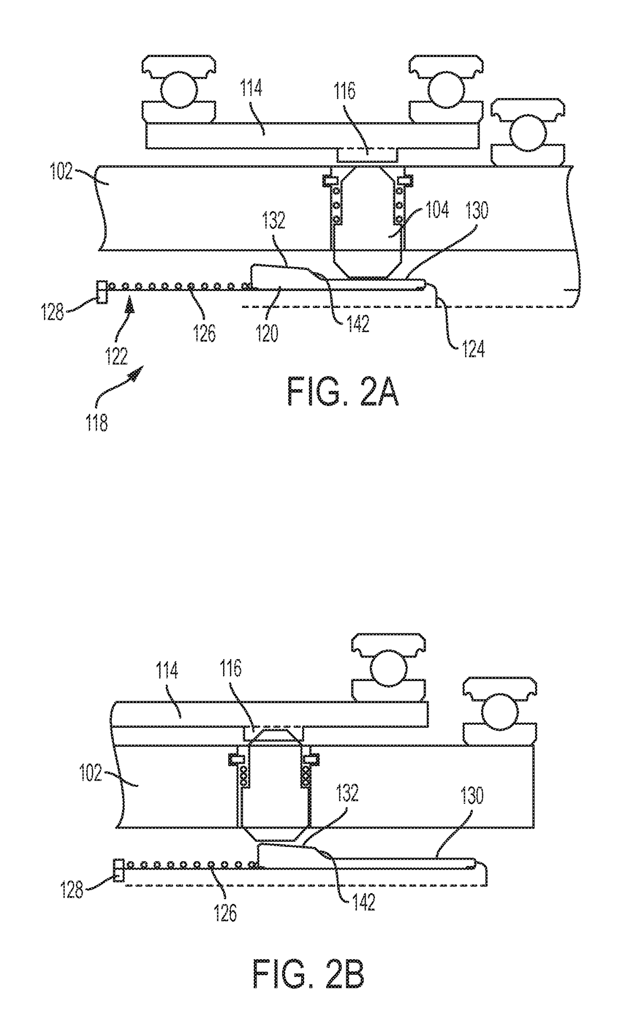
[0040]Referring now to FIGS. 1 through 2B, operation of the dog clutch 100 and additional detail regarding the actuator 118 is explained. The actuator 118 includes a bullet actuator 120 concentrically mounted on an actuating shaf...


PUM


Abstract

A dog clutch for a vehicle transmission includes a driving member configured to rotate about an axis and including a cavity extending radially from the axis, a driving tooth slidably movable within the radially extending cavity, a driven member coaxially surrounding the driving member and including a radially inward extending driven tooth axially aligned with the driving tooth, an actuator shaft coaxially positioned within the driving member and movable along the axis, a retainer on the actuator shaft, a bullet actuator coaxially mounted on the actuator shaft, and a biasing member coaxially mounted on the actuator shaft and positioned between the bullet actuator and the retainer.

Description

FIELD[0001]The present disclosure relates to a radially applied dog clutch with bi-directional ratcheting for a vehicle transmission.INTRODUCTION[0002]This introduction generally presents the context of the disclosure. Work of the presently named inventors, to the extent it is described in this introduction, as well as aspects of the description that may not otherwise qualify as prior art at the time of filing, are neither expressly nor impliedly admitted as prior art against this disclosure.[0003]Clutches are commonly found in automotive transmissions. Friction clutches are most common, but suffer from a number of disadvantages. Friction clutches suffer from spin losses and pump losses. Friction clutches typically require a high pressure hydraulic system to control operation of the clutch. The energy consumed by the pump(s) that provide the source for high pressure hydraulic fluid can adversely affect the efficiency of a vehicle incorporating a transmission that includes friction c...

Claims


Application Information

Patent Timeline
Patent Type & Authority Applications(United States)
IPC IPC(8): F16D11/16F16D23/12
CPCF16D11/16F16D2023/123F16D23/12F16D41/16F16D23/06F16D2023/0618F16D2300/24
Inventor LITTLEFIELD, JOSEPH R.BOYD, JONATHAN
Owner GM GLOBAL TECH OPERATIONS LLC
Why Eureka
Try Eureka