
Method of performing uplink transmission in wireless communication system and apparatus therefor

Active Publication Date: 2018-08-16
LG ELECTRONICS INC
View PDF6 Cites 61 Cited by
  • Summary
  • Abstract
  • Description
  • Claims
  • Application Information

AI Technical Summary

Benefits of technology

The patent is about improving wireless communication by using specific beams for uplink and downlink channels. The terminal device's pre-determined uplink beam is determined based on the best downlink beam for reception. Additionally, the patent proposes a hierarchical approach for selecting the optimal beam, which reduces the time and control overhead for beam change. As a result, the network can better utilize multiple beams for communication, leading to improved performance and reliability.

Problems solved by technology

However, since the service range of mobile communication system extended has been extended to data service as well as voice service, current explosive traffic increase causes lack or resources, and users require faster services, enhanced mobile communication systems are needed.

Method used


Image

  • Method of performing uplink transmission in wireless communication system and apparatus therefor
  • Method of performing uplink transmission in wireless communication system and apparatus therefor
  • Method of performing uplink transmission in wireless communication system and apparatus therefor

Examples


first embodiment

ting Tx Beam of UE Through DCI and / or Higher Layer Signaling

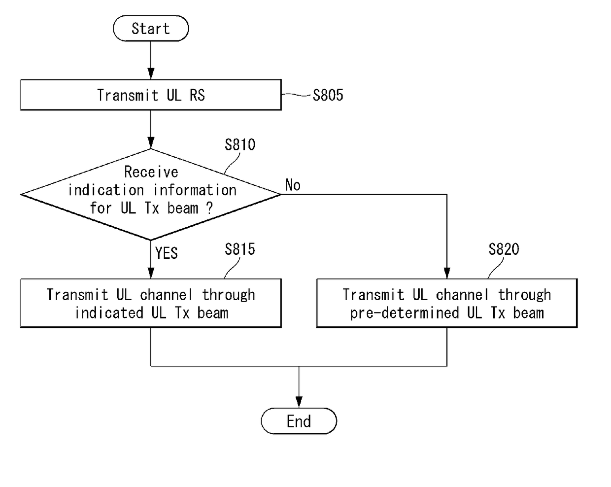
[0217]As described above, a method of transmitting, by a BS, information about Tx beams (i.e., UL Tx beams) of a UE determined through a UL beam management procedure to the UE through DCI and / or higher layer signaling may be considered. The method may be divided into a method of transmitting the information through DCI (method 1), a method of transmitting the information using higher layer signaling (method 2) and a method of transmitting the information using both DCI and higher layer signaling (method 3) according to used information and / or signaling. Here, method 3 (i.e., the method of transmitting the information using higher layer signaling) may refer to a method of hierarchically indicating information about UL Tx beams of the UE.

[0218]In this case, for robustness of an uplink control channel, the BS may indicate different Tx beams for the uplink control channel (e.g., PUCCH) and an uplink data channel (e.g., PUSCH). ...

second embodiment

ing Tx Beam of UE According to UL RS Configuration

[0247]The BS may configure a UL RS in consideration of UE capability (e.g., the number of UL Tx beams of a UE, the number of transmission and reception units (TXRU) of the UE, etc.) for UL beam management. Here, the BS may perform a UL Tx beam indication procedure according to UL RS configuration. In other words, the BS may indicate UL Tx beams for a UE on the basis of UL RS configuration (or for each UL RS configuration).

[0248]When the number (e.g., M) of UL Rx beams of the UE is equal to or greater than a predetermined number, the BS may configure (or allocate) a UL RS over a plurality of slots instead of one slot (or subframe). Here, the BS may be configured to perform Tx beam indication (i.e., UL Tx beam indication of the UE) for each UL RS transmission. In this case, ambiguousness with respect to whether the UE needs to transmit an uplink channel using previous UL Tx beams or newly indicated UL Tx beams for each Tx beam indicati...


PUM


Abstract

In the present invention, a method for performing an uplink transmission in a wireless communication system and an apparatus for supporting the same are disclosed. Particularly, a method for transmitting an uplink control channel in a wireless communication system by a terminal may comprise receiving, from a base station, beam information regarding one or more beams for transmitting a physical uplink control channel (PUCCH), via a radio resource control (RRC) signaling; receiving, from the base station, beam indication information indicating a specific beam among the one or more beams using a medium access control-control element (MAC-CE); and transmitting, to the base station, the physical uplink control channel using the specific beam.

Description

CROSS-REFERENCE TO RELATED APPLICATIONS[0001]This application claims the benefit of U.S. Provisional Application No. 62 / 454,804, filed on Feb. 5, 2017 and U.S. Provisional Application No. 62 / 505,102, filed on May 11, 2017.[0002]The contents of this application are hereby incorporated by reference in its entirety.BACKGROUND OF THE INVENTIONField of the Invention[0003]The present invention relates to a wireless communication system and, more specifically, to a method for indicating an uplink transmission beam for uplink transmission of a terminal, and an apparatus for supporting the same.Related Art[0004]Mobile communication systems have been developed in order to provide voice service while securing user mobility. However, since the service range of mobile communication system extended has been extended to data service as well as voice service, current explosive traffic increase causes lack or resources, and users require faster services, enhanced mobile communication systems are nee...

Claims


Application Information

Patent Timeline
IPC IPC(8): H04W72/04
CPCH04W72/046H04W72/042H04L1/16H04W72/20H04W72/23
Inventor AHN, MINKIKANG, JIWONKIM, KIJUNPARK, JONGHYUNPARK, CHANGHWANYI, YUNJUNG
Owner LG ELECTRONICS INC
Learn More