Control device for electric vehicle and control method for electric vehicle

a technology for electric vehicles and control devices, which is applied in the direction of braking systems, battery/fuel cell control arrangements, braking components, etc., can solve the problems of excessive battery charge and electric vehicle cannot be smoothly stopped

Active Publication Date: 2018-08-30
NISSAN MOTOR CO LTD
View PDF0 Cites 11 Cited by
  • Summary
  • Abstract
  • Description
  • Claims
  • Application Information

AI Technical Summary

Benefits of technology

[0005]It is an object of the present invention to provide a technique that solves a problem that an electric vehicle cannot be smoothly stopped when a battery is in a full charge state.

Problems solved by technology

insofar as the battery is in the full charge state, if the regenerative braking is performed, the battery is excessively charged.
Therefore, there is a problem that the electric vehicle cannot be smoothly stopped.

Method used


Image

  • Control device for electric vehicle and control method for electric vehicle
  • Control device for electric vehicle and control method for electric vehicle
  • Control device for electric vehicle and control method for electric vehicle

Examples


first embodiment

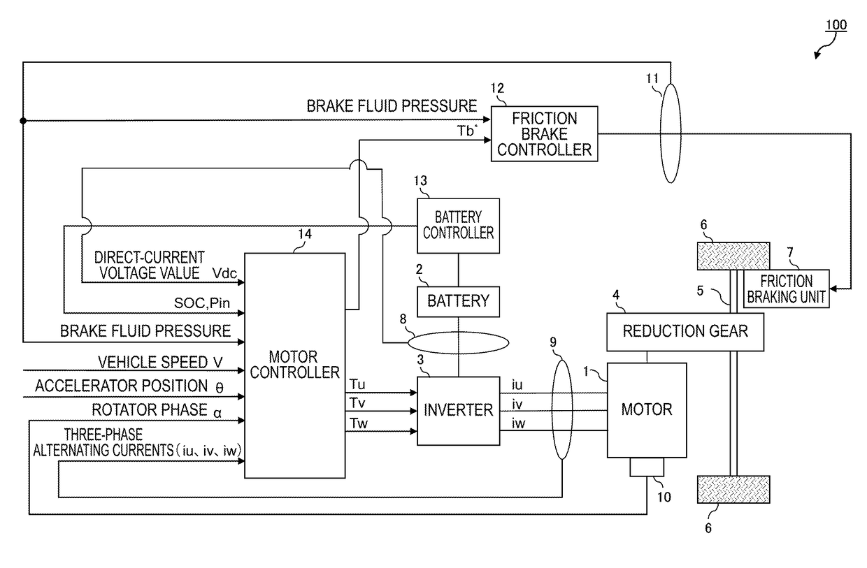
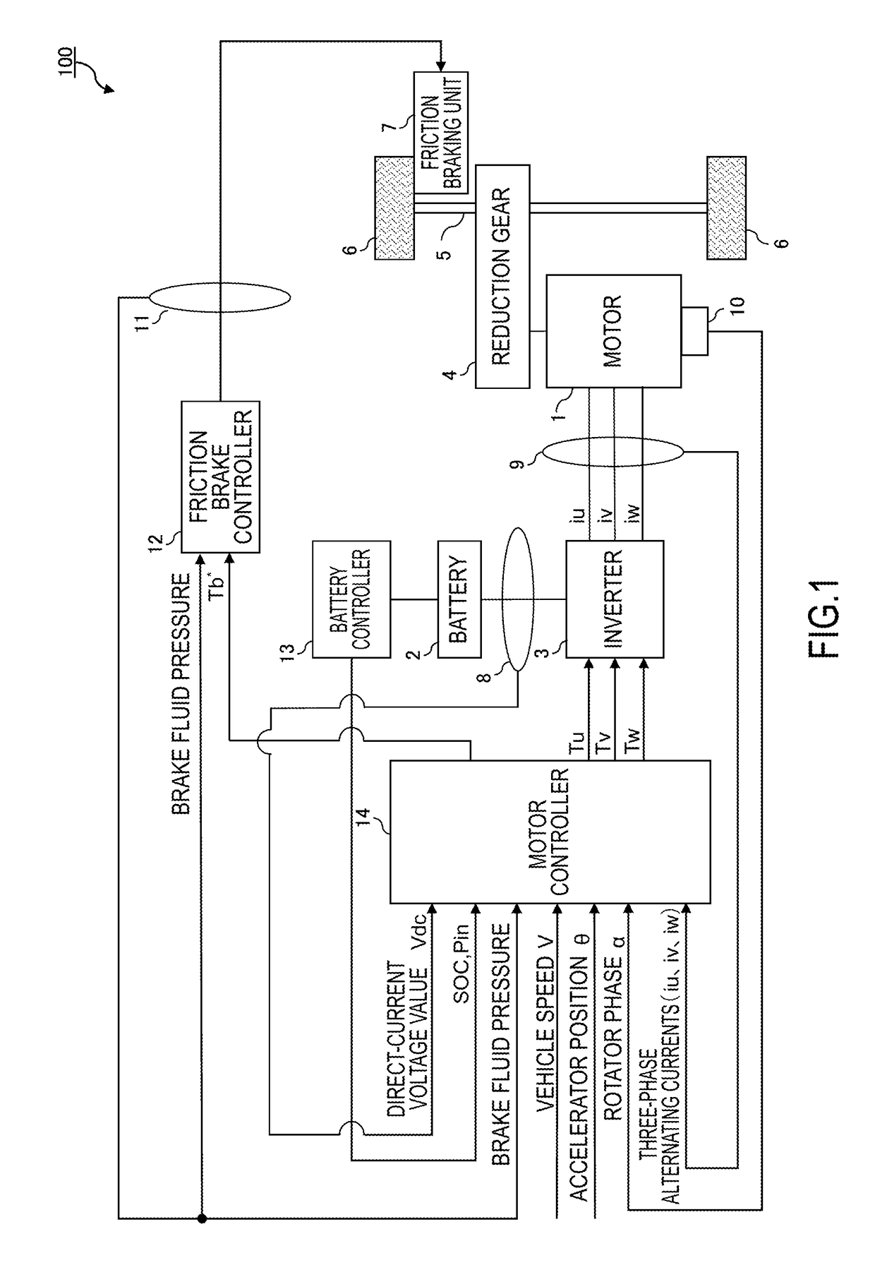
[0029]FIG. 1 is a schematic configuration diagram of an electric vehicle 100 that includes a motor controller 14 as a control device according to the first embodiment.

[0030]The electric vehicle 100 includes a motor 1 as a part of or the entire driving source. In this embodiment, it is assumed that the motor 1 mounted to the electric vehicle 100 operates in three-phases (U, V, and W phases). It should be noted that the electric vehicle 100 may be an electric vehicle that uses an electric motor as a driving source and a hybrid vehicle that uses an electric motor and an engine as driving sources.

[0031]The electric vehicle 100 according to the embodiment can perform acceleration and deceleration and stop only by operating an accelerator pedal. That is, a driving torque and a regenerative torque generated by the motor 1 are determined according to an opening degree of the accelerator pedal. Therefore, an increase in the opening degree of the accelerator pedal increases the driving torque...

second embodiment

[0225]The following describes a control device of a second embodiment. This embodiment describes a case where a timing that the braking method switches from the friction braking to the regenerative braking is different from that in the first embodiment.

[0226]FIG. 15 is a configuration diagram of an electric vehicle 100 including a motor controller 14 as the control device of the second embodiment.

[0227]With reference to FIG. 15, the electric vehicle 100 of the second embodiment is different from the electric vehicle 100 of the first embodiment illustrated in FIG. 1, in that the regenerable electric power Pin is not output from the battery controller 13 to the motor controller 14.

[0228]The motor controller 14 preliminarily stores an SOC specified value (SOC0) used for obtaining a switching timing between the friction braking and the regenerative braking. It should be noted that the SOC specified value (SOC0) can be obtained as follows.

[0229]First, a charging electric energy of the ba...

third embodiment

[0265]Next, a description will be given of the electric vehicle 100 that includes a control device of a third embodiment. In the second embodiment, as the specified charging electric energy Ws0, a regenerative electric energy generated between a time point at which the electric vehicle 100 becomes in the state of just before stop of the vehicle and a time point at which the vehicle stops is preliminarily predicted. In this embodiment, a description will be given of an example where the charging electric energy Ws is predicted corresponding to a running state of the electric vehicle 100.

[0266]The electric vehicle 100 of the third embodiment has a configuration identical to the configuration of the electric vehicle 100 of the first embodiment illustrated in FIG. 1. Then, the explanation of the configuration will be omitted.

[0267]When this embodiment is compared with the first embodiment, the processes illustrated in FIG. 3, FIG. 5, FIG. 6, and FIG. 7 are identical, and the command val...


PUM


Abstract

A control device is provided for an electric vehicle that generates a braking force corresponding to an opening degree of an accelerator pedal to decelerate the electric vehicle. The control device for the electric vehicle includes a motor configured to generate a driving force or a regenerative braking force of the electric vehicle, a friction braking unit configured to generate a friction braking force, and a controller configured to control at least one of the motor and the friction braking unit corresponding to the opening degree of the accelerator pedal. The controller determines whether all of regenerative electric power generated by the motor is consumed in the electric vehicle when the motor is caused to perform a regenerative braking. The controller causes the motor to perform the regenerative braking when the regenerative electric power is determined to be consumed in the electric vehicle.

Description

TECHNICAL FIELD[0001]The present invention relates to a control device for an electric vehicle and a control method for the electric vehicle.BACKGROUND ART[0002]Braking force used when an electric vehicle is decelerated or stopped is obtained from regenerative braking by a motor and friction braking by a brake. The regenerative braking has a better controllability of the braking force than that of the friction braking. Thus, to smoothly stop the electric vehicle, it is preferable to stop the vehicle by the regenerative braking, not by the friction braking. Especially, in a vehicle that performs driving and braking of the motor according to an opening degree of an accelerator pedal, it is necessary to stop the vehicle by adjusting the braking force according to disturbance. Thus, it is preferable to perform the regenerative braking having good controllability just before stop of the vehicle.[0003]However, conventionally, if the regenerative braking is performed when a battery is in a...

Claims


Application Information

Patent Timeline
Patent Type & Authority Applications(United States)
IPC IPC(8): B60L7/26B60W10/184B60W30/18B60W10/08B60L7/18B60L11/18
CPCB60L7/26B60W10/184B60W30/18127B60W10/08B60L7/18B60L11/1851B60W2520/04B60W2540/10B60W2710/18B60L2240/16B60L2240/423B60L7/24B60L7/10B60T2270/604B60T2270/60B60W10/18B60W30/18109B60W2510/244B60W2510/305B60L58/10Y02T10/72Y02T10/70
Inventor HIRAKAWA, YOICHIITOU, KENKATSUMATA, YUJIKOMATSU, HIROYUKI
Owner NISSAN MOTOR CO LTD
Why Eureka
Try Eureka