
Method for controlling compression system, compression system, and hydrogen station

a compression system and hydrogen station technology, applied in the direction of machines/engines, positive displacement liquid engines, greenhouse gas reduction, etc., can solve the problems of long work and great effort, and achieve the effect of smooth return and smooth stoppage of gas processing

Active Publication Date: 2021-06-15
KOBE STEEL LTD
View PDF12 Cites 0 Cited by
  • Summary
  • Abstract
  • Description
  • Claims
  • Application Information

AI Technical Summary

Benefits of technology

[0005]The paragraph 0052 describes “The control unit 28 having started the stop control of the compressor 22 in Step ST3 executes a close control to close the out-flow side on-off valve 233a (Step ST4).” The stop control reduces the processing amount of the compressor 22, whereby the amount of hydrogen gas sent to the accumulator may decrease, and closing the out-flow side on-off valve 233a may cause a large amount of hydrogen gas to accumulate on the discharge side of the compressor 22.
[0026]As is apparent from the above description, according to the present invention, it is possible to provide a method for controlling a compression system and a compression system, and a hydrogen station including the compression system which are capable of smoothly stopping the processing of gas by a compressor.

Problems solved by technology

Further, in JP 2017-131862 A, the compressor is stopped, so that the compressor is required to be restarted in order to refill the accumulator with the hydrogen gas, thus resulting in long work and great effort.

Method used


Image

  • Method for controlling compression system, compression system, and hydrogen station
  • Method for controlling compression system, compression system, and hydrogen station
  • Method for controlling compression system, compression system, and hydrogen station

Examples


first embodiment

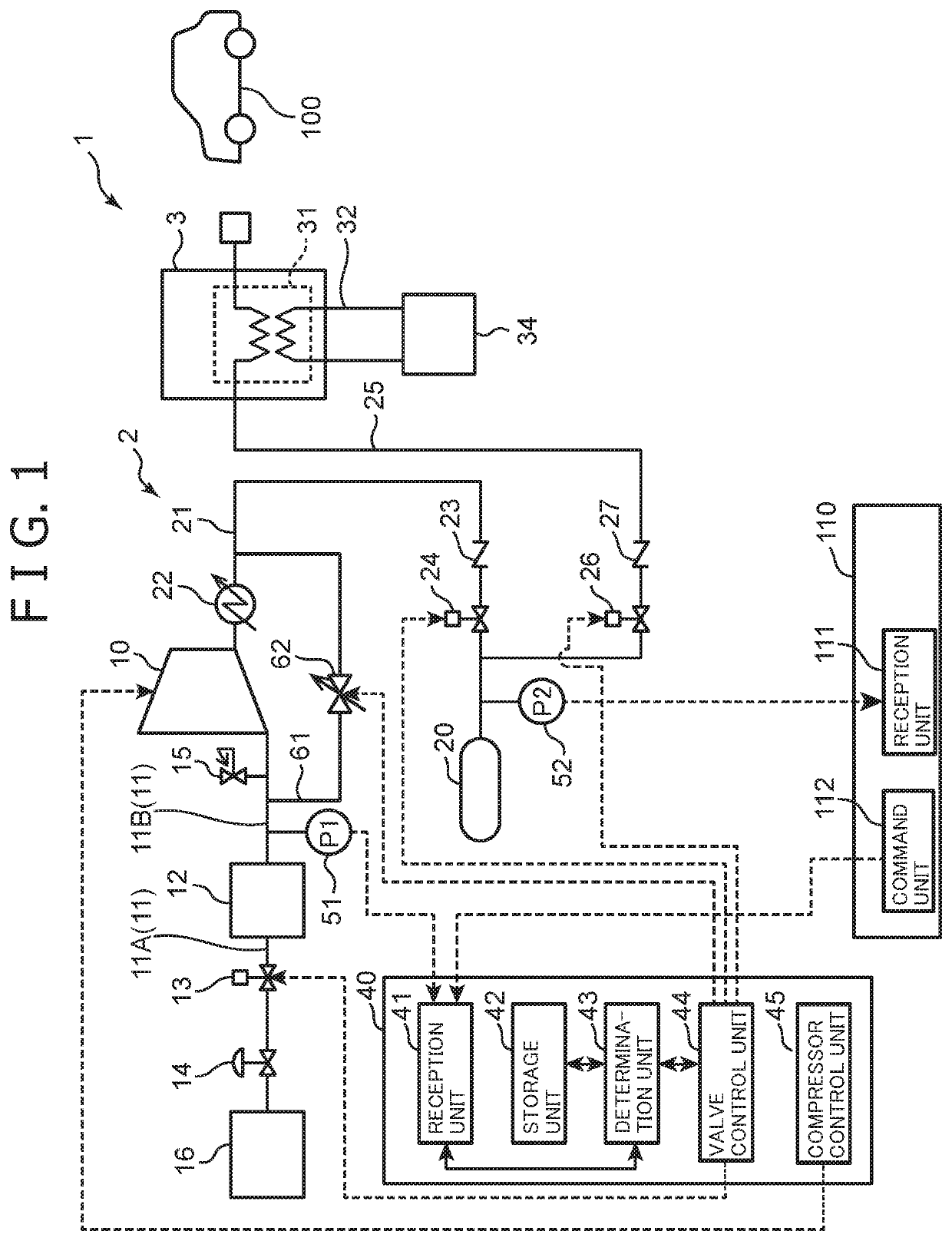
[0031]The configuration of a compression system 2 and a hydrogen station 1 including the compression system 2 according to a first embodiment of the present invention will be first described with reference to FIG. 1. The hydrogen station 1 is a facility for refueling a fuel cell vehicle 100 with hydrogen gas as a fuel, and mainly includes the compression system 2 and a dispenser 3.

[0032]The compression system 2 compresses the hydrogen gas supplied from a trailer tank 16 and supplies it to the dispenser 3. As shown in FIG. 1, the compression system 2 mainly includes a compressor 10, a suction flow passage 11, a buffer tank 12, a first on-off valve 13, a pressure reducing valve 14, a safety valve 15, a first pressure detection section 51, and a discharge flow passage 21, a cooler 22, a check valve 23, a second on-off valve 24, a second pressure detection section 52, an accumulator 20, a bypass flow passage 61, a bypass valve 62, and a compression system control unit 40. Hereinafter, e...

second embodiment

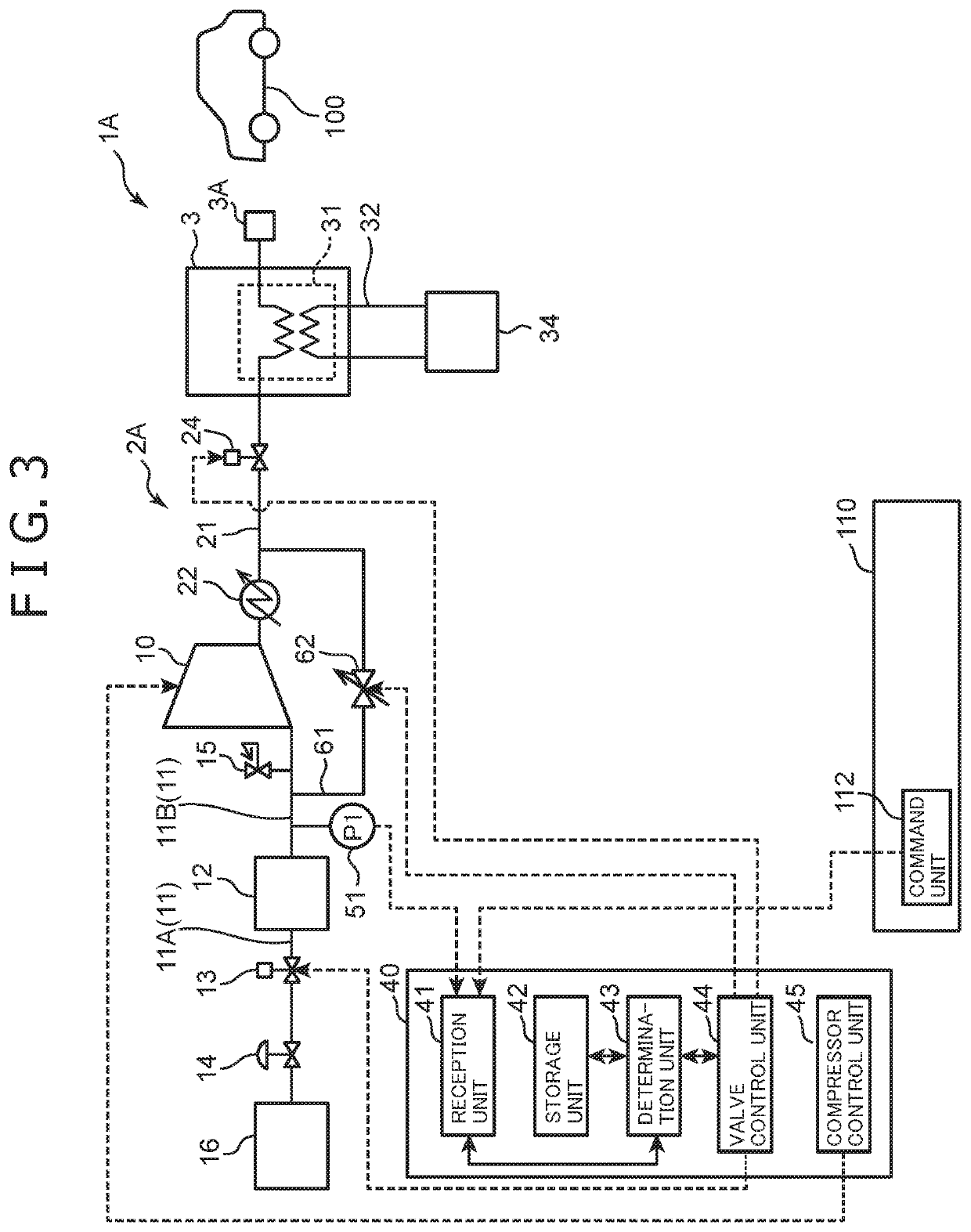
[0074]Next, a second embodiment of the present invention will be described based on FIG. 3. The second embodiment is basically the same as the first embodiment, but is different from the first embodiment in that the accumulator 20 is not provided and hydrogen gas is directly supplied from the compressor 10 to the dispenser 3. Only the difference from the first embodiment will be described below. In addition, in FIG. 3, the same components as those of the first embodiment (FIG. 1) are denoted by the same reference numerals, and the description thereof will be omitted.

[0075]As shown in FIG. 3, in a hydrogen station 1A according to the second embodiment, the discharge flow passage 21 has an upstream end connected to the discharge port of the compressor 10 and a downstream end connected to the inlet of the dispenser 3. Therefore, the hydrogen gas compressed by the compressor 10 is supplied to the dispenser 3 through the discharge flow passage 21, is cooled by the brine in the precooler ...


PUM


Abstract

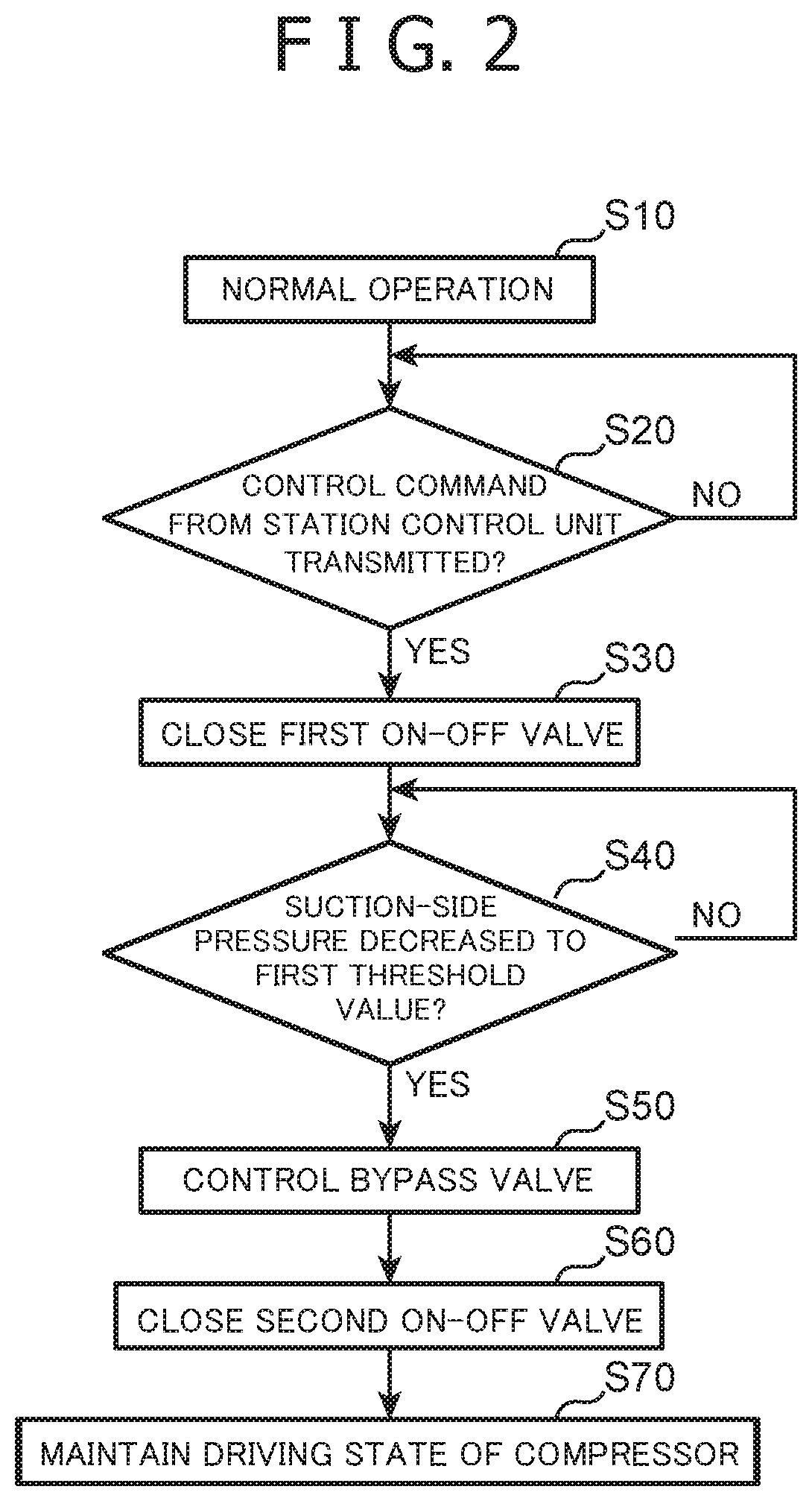
A method for controlling a compression system that includes a compressor for compressing gas, a first on-off valve provided on a suction flow passage connected to a suction side of the compressor, a pressure reducing valve provided on a portion of the suction flow passage upstream of the first on-off valve, a second on-off valve provided on a discharge flow passage connected to a discharge side of the compressor, a bypass flow passage connecting the suction flow passage and the discharge flow passage to detour the compressor, and a bypass valve provided on the bypass flow passage, includes closing the first on-off valve while driving the compressor, opening the bypass valve simultaneously with or after the closing of the first on-off valve, closing the second on-off valve after the opening of the bypass valve, and continuing to drive the compressor after the closing of the second on-off valve.

Description

BACKGROUND OF THE INVENTIONField of the Invention[0001]The present invention relates to a method for controlling a compression system, a compression system, and a hydrogen station including the compression system.Description of the Related Art[0002]Conventionally, as described in JP 2017-131862 A, in a hydrogen station, a compression system is known which compresses hydrogen gas as a fuel and supplies the compressed hydrogen gas to a dispenser. The compression system has a compressor for compressing hydrogen gas and an accumulator arranged downstream thereof, and is configured to temporarily store the compressed hydrogen gas in the accumulator, and then be capable of supplying the hydrogen gas from the accumulator to the dispenser. Specifically, the compression system described in JP 2017-131862 A includes a compressor, a suction flow passage connected to a suction side of the compressor, an on-off valve provided on the suction flow passage, and a discharge flow passage connected to...

Claims


Application Information

Patent Timeline
Patent Type & Authority Patents(United States)
IPC IPC(8): F17C5/06F04B41/02
CPCF17C5/06F04B41/02F17C2205/0335F17C2221/012F17C2250/032F17C2250/043F17C2250/0636F17C2270/0184F04B49/035F04B49/24F04B49/065F04B2205/07F04B2205/01Y02E60/32Y02E70/30F17C2223/0123F17C2223/036F17C2225/0123F17C2225/036F17C2227/0157F17C2265/065F17C2250/01F17C2250/0439F17C2205/0332F17C2205/0338F17C2227/0348
Inventor HASHIMOTO, KOICHIROTAKANO, MASASHIUBA, TAKUROFUKUDA, TAKAYUKINAGURA, KENJI
Owner KOBE STEEL LTD
Learn More